
LED Knight RiderCircuit With 4017 and 555 IC

The LED Knight Rider circuit is designed to create a visual effect reminiscent of the iconic "Knight Rider" television series, where lights move back and forth in a sequential pattern. The core components of this circuit are the 555 timer IC, which operates in astable mode to generate a continuous pulse, and the 4017 decade counter IC, which is used to drive the LEDs in a sequence.
In this circuit, the 555 timer is configured to produce a clock signal that toggles at a predetermined frequency. This frequency can be adjusted by varying the resistor and capacitor values connected to the 555 timer. The output of the 555 timer is fed into the clock input of the 4017 IC, which counts the pulses and activates the corresponding outputs in a sequential manner.
The 4017 IC has ten output pins, but in this specific design, only four outputs are utilized to control four LEDs. As the 4017 counts the pulses from the 555 timer, it sequentially turns on each LED one after the other, creating the desired running light effect. When the last LED is turned on, the 4017 resets, and the cycle begins again, resulting in a continuous back-and-forth movement of the lights.
The circuit requires a power supply, typically in the range of 5V to 15V, depending on the specifications of the components used. The LEDs can be connected in series with current-limiting resistors to prevent excessive current flow, ensuring their longevity. Overall, this circuit is an excellent demonstration of basic digital electronics principles and provides a visually appealing effect for various applications.The following circuit shows about LED Knight Rider Circuit Diagram. This circuit based on the 4017 and 555 IC. Features: Knight Rider circuit, 4 .. 🔗 External reference
Related Circuits
The title contains numerous words because this instructable integrates various concepts from multiple sources. The primary idea originated from Robomaniac's Desktop Energy Seed Lamp, combined with Witch's Growing Plants with LED Lights instructable and various wick gardening planters. The...
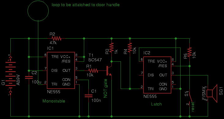
Security has become a significant concern in today's world, leading to the availability of various security gadgets. This document introduces a simple touch alarm designed specifically for doors with metallic handles. The alarm functions exclusively on metallic handles and...

The objective of the circuit is to create an electronic dice using the functionality of a 555 timer integrated circuit operating in astable mode. The electronic dice circuit utilizes a 555 timer configured in astable mode to generate a series...

The circuit schematics operate at 12 Volts, sourced from a car battery. The ground connection is tied to the car chassis, while the signal is received from a sensor connected to a stepper motor. The No. 5 pin of...

The circuit depicted involves transistors VT1, VT2, and resistor R1, which form a constant current source for charging capacitor C2 in a linear manner. Transistors VT3, VT4, and resistor R2 create a constant current source for discharging capacitor C2,...
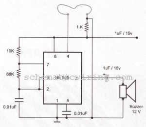
The circuit of a burglar alarm utilizing IC timer 555/556 functions as a security measure to prevent unauthorized entry into a premises. The alarm generates a loud sound when a thin wire connecting resistor R1 with pin 4 of...