
Block Transistor Radio

The Breadboard Six Transistor Radio Kit is designed for ease of assembly and accessibility to hobbyists and beginners in electronics. The use of a breadboard allows for a non-permanent setup, making it ideal for educational purposes and experimentation. The terminal strip connections eliminate the need for soldering, which can be a barrier for those new to electronics. Each component is carefully selected to ensure compatibility and performance, providing a satisfactory listening experience comparable to commercially available AM radios.
The schematic diagram, while initially intimidating, serves as a valuable guide throughout the assembly process. It delineates the connections and relationships between components, which can be particularly useful for those with more experience in circuit design. For novices, the emphasis should be placed on following the visual instructions and ensuring that connections are made correctly, rather than fully understanding the underlying electronic principles at the outset.
The inclusion of a comprehensive parts list with links to images aids in component identification, ensuring that builders can easily locate and verify the correct parts before assembly. This resource is particularly beneficial for those unfamiliar with electronic components and their specifications.
Overall, the Breadboard Six Transistor Radio Kit represents an engaging project that combines practical electronics skills with the satisfaction of creating a functional radio receiver. Proper adherence to the assembly instructions will result in a successful build, providing a rewarding experience for both novice and experienced electronics enthusiasts.If you prefer a version that is quicker and easier to build, but which doesn`t have quite the same final appearance I highly recommend the Breadboard Six Transistor Radio Kit. It is also slightly cheaper. This is a MW AM transistor radio which can be constructed without soldering using 3A terminal strip. It is a modern response to the 1971 Ladybird Book Radio and works as well as some AM radios that you could buy in a shop. It`s best to read right through the construction notes first before starting out. Why is it called a Choccy Block Radio Kit Choccy-Block is the nickname for the terminal strips on which it is constructed, and they look rather like chocolate bars. I supply a kit of all the electronic parts, wire, terminal blocks, knobs, mounting screws and a cardboard enclosure for this design with wires soldered on to some parts where necessary.
I`ve assumed that you have a small screwdriver for the terminal screws, a fine point marker pen, some small wire cutters for trimming the component leads and some means of stripping the insulation from the wire. A craft knife is good for that. You will also need some paper, glue, scissors and sticky tape. It is best to mount up the radio in an enclosure when it is all working. The cardboard container supplied is pretty good to start with, or you might choose to use some other method.
The components list has links to photographs that should allow you to make sense of the different values and to identify which leg is which. You need to know about resistor colour codes and you can find that information in many places. It should be possible to build the radio just by looking at the pictures, but later on I`ve included full electronic explanations.
If those don`t make any sense, don`t let them put you off just building the circuit. The schematic diagram can look a bit daunting to the novice. Don`t Panic. You don`t need to understand it all to make it work. The idea of this design is that if you follow the plan it should work without too much fiddling. Experienced builders will find the schematic diagram helpful as well. Start by cutting to length, stripping the ends and assembling the single core link wires into the terminal strips as shown. Each wire must have the end stripped of insulation by about 6mm so that the terminal strip screw touches the bare wire.
It is best if each wire end is only trapped under one screw on the side which it enters the strip. For now, tighten the screws only very gently, just enough to hold the wires in while you put everything else together. As long as they are in the correct holes, the wires don`t have to be absolutely in the exact shapes shown, but it will make it easier to check everything later on if it`s made just like in the picture.
You can click on the pictures to see a bigger version. Identify the various different transistors and bend their legs as shown in the BOM pictures so that they will fit into the strips. The transistor legs will only bend a few times before dropping off, so it`s best to get it right first time.
Assemble the two diodes in the positions shown, so that the glass bodies are in contact with the transistors but so that the wires are not touching the metal part. The diodes and transistors have to be connected the correct way round as shown by the identification letters next to the legs.
Note that Q4 is connected with the curved side facing upwards and the flat side facing down. You can fit the resistors either way round, but it will be easier to check later if the gold coloured bands are pointing down or to the right. R8 requires an extra loose terminal block to connect it to VR1. In the next stage, fit both the ceramic disc and electrolytic capacitors. With the exception of the bipolar one, the electrolytic capacitors have to be connected the correct way round.
Now that things are getting a bit crowded, you might find that keeping the capacitor wires from touching 🔗 External reference
Related Circuits
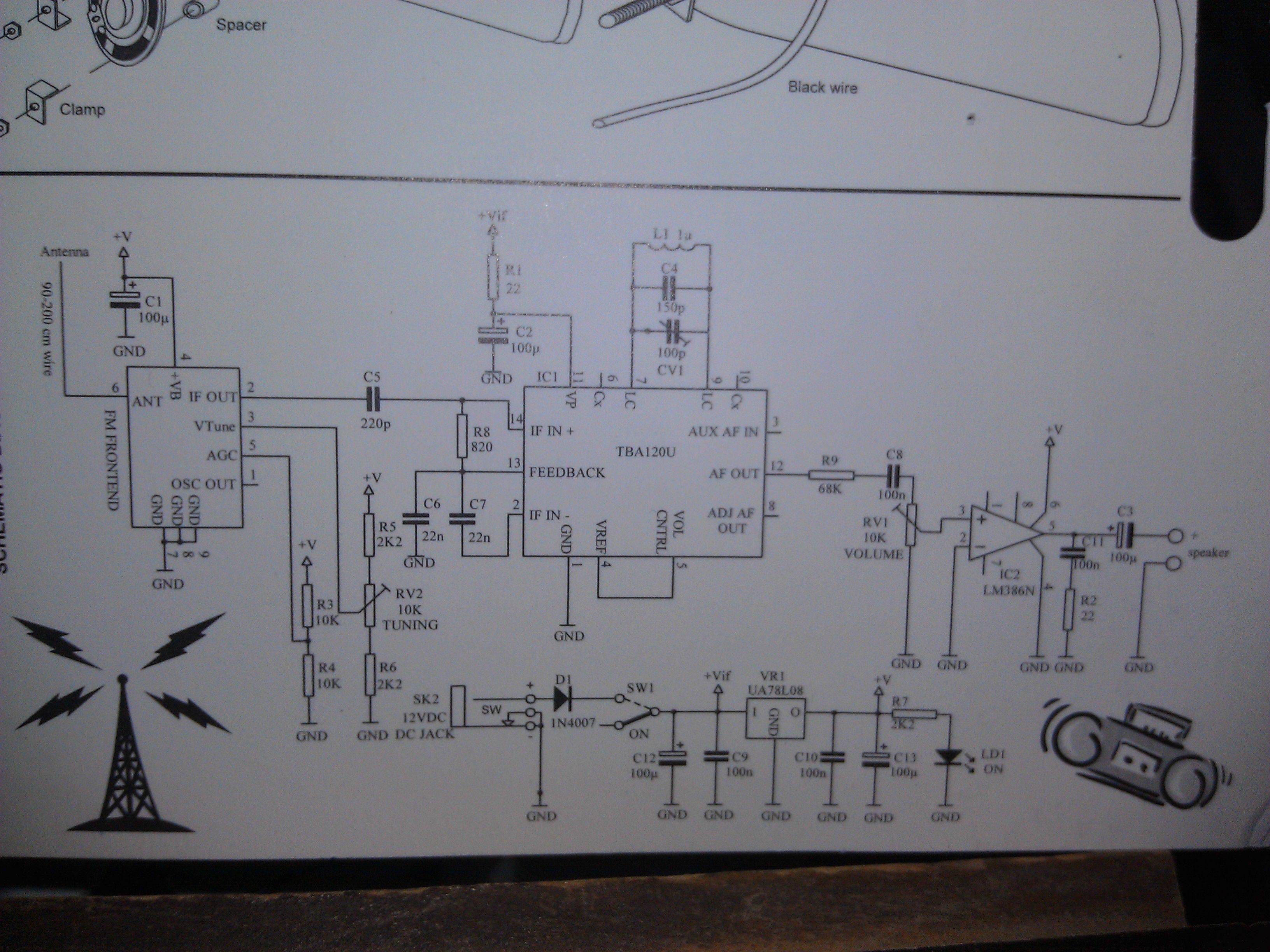
An FM Radio kit manufactured by Velleman-Kit and sold by Radioshack was recently assembled. The assembly process took approximately two hours, primarily due to distractions. The instructions provided are generally easy to follow, but they lack explicit details regarding...
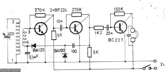
Oscillating circuits (coils) are constructed on a ferrite bar. For long wave reception, winding "1-2" consists of 135 turns, while winding "3-4" has 20 turns. For medium wave reception, winding "1-2" has 75 turns, and winding "3-4" has 7...
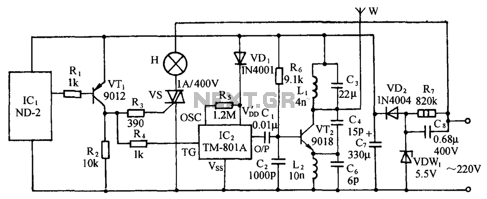
The circuit includes a comprehensive array of components such as vibration sensors, a follower, a lamp relay control circuit, a voice sounding circuit, a high-frequency oscillation circuit, and an AC rectifier buck power supply circuit. The vibration sensor is...
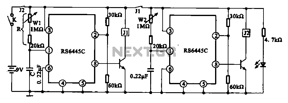
The timing integrated circuit (IC) RS6445C functions as a blocking oscillator. It features two segments, WI and W2, which are utilized to adjust the working time and the closure time. These adjustments can be continuously set within a range...
The AM signal is captured by the antenna, 10 mt long horizontal wire, WELL insulated from earth. The inductor and capacitor form a resonator, that will tune with the station whose frequency is F = 1 / (2 *...
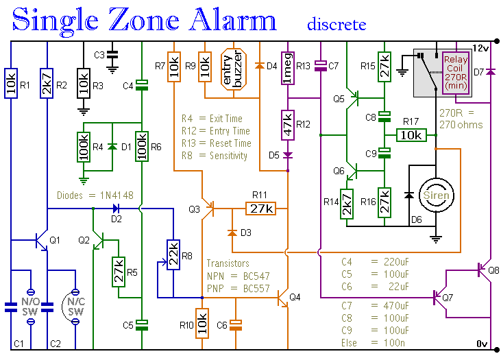
The circuit incorporates automatic exit and entry delays, a timed bell cut-off, and a system reset feature. It accommodates both normally-open and normally-closed switches and is compatible with standard input devices such as pressure mats, magnetic reed contacts, foil...