
radio receiver circuit long and medium wave

The described oscillating circuit utilizes a ferrite bar as the core material, which enhances the inductance of the coils and improves the circuit's efficiency in receiving radio waves. The choice of 135 turns for winding "1-2" in the long wave configuration and 75 turns in the medium wave configuration indicates a design optimized for different frequency ranges. The number of turns directly affects the inductance and resonant frequency of the circuit, which is crucial for effective signal reception.
The use of CuEm wire with a diameter of 0.15 mm is significant as it provides the necessary conductivity while maintaining a manageable physical size for the windings. The wire's resistance and skin effect at radio frequencies must be considered, ensuring the circuit operates effectively across the intended frequency bands.
Incorporating a variable capacitor of 40-400 pF in parallel with winding "1-2" allows for fine-tuning the resonant frequency of the circuit. This adjustability is essential for optimizing reception and selecting specific stations within the long or medium wave bands. The variable capacitor should be carefully selected to ensure it can handle the voltage and current levels present in the circuit.
The high-impedance headphones rated at 1000-2000 ohms are suitable for this application, as they are designed to work with low-power audio signals generated by the oscillating circuit. The inclusion of a 10 nF capacitor in parallel with the headphones serves to filter out any high-frequency noise and improve the overall sound quality, allowing for clearer audio reception.
Overall, this oscillating circuit design is a practical approach for listening to long and medium wave radio frequencies, combining specific coil configurations, a variable capacitor, and high-impedance headphones to achieve effective signal reception.Oscillating circuit (coil) are made on a ferrite bar. If you wish to listen long waves winding "1-2" has 135 turns and 3-4 has 20 turns. If you wish to receive medium wave winding "1-2" has 75 turns, and "3-4" has 7 turns (wire used must be CuEm 0. 15mm). In parallel with the winding 1-2 is necessary to connect a 40-400pF variable capacitor. Listen ing signal is made using high impedance headphones to 1000-2000 ohms, which have a capacitor of 10nF in parallel. 🔗 External reference
Related Circuits
The DTMF codec stands for dual-tone multi-frequency codec. The multiple-channel infrared remote control switch circuit that incorporates the DTMF is depicted in the figure. It consists of an infrared remote control signal emitter, an infrared receiving signal amplifier, a...
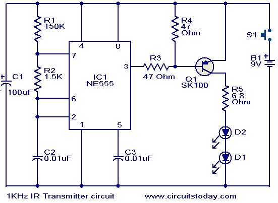
This circuit was designed in response to a request for a 1 kHz infrared (IR) transmitter circuit suitable for remote control applications. It is intended to serve as a low-power IR transmitter with an operating frequency of 1 kHz,...
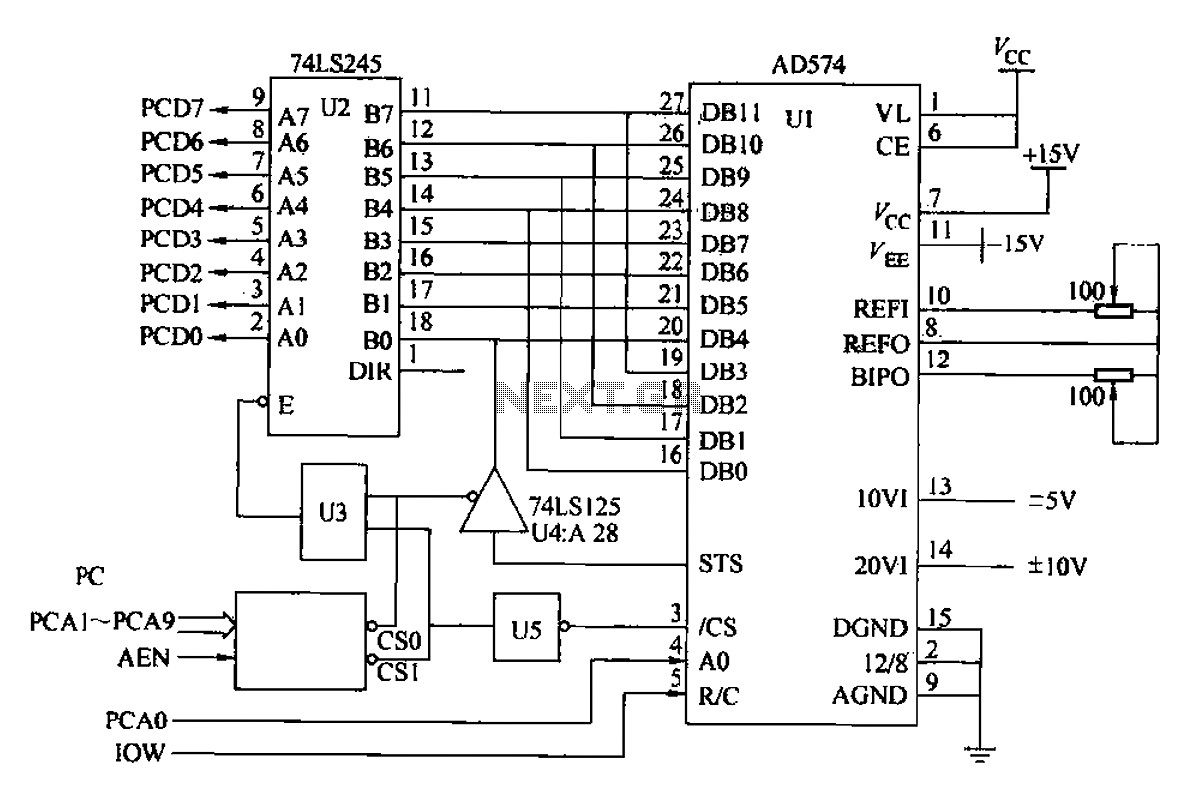
Another example is provided using the AD574 and PC bus. The AD574 converter is represented by U1, while U2 is a 74LS245 bidirectional data buffer. U3 is a 74LS00 two-input AND gate, U4 is a 74LS125 tri-state output gate,...
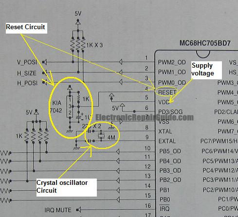
The difference between these two ICs. A microcontroller is a specialized type of microprocessor designed to be self-sufficient and cost-effective, while a microprocessor is typically intended for general-purpose use, such as in personal computers (PCs). The microcontroller integrates several...
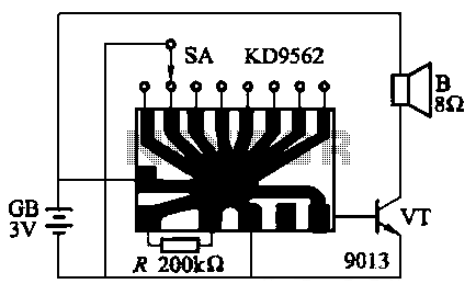
The KD9562 music octave circuit is an analog sound circuit capable of producing various sound effects including rifle shots, space shots, game console sounds, dual-tone doorbells, bomb explosions, machine gunfire, and ambulance sirens. The main electrical parameters are as...
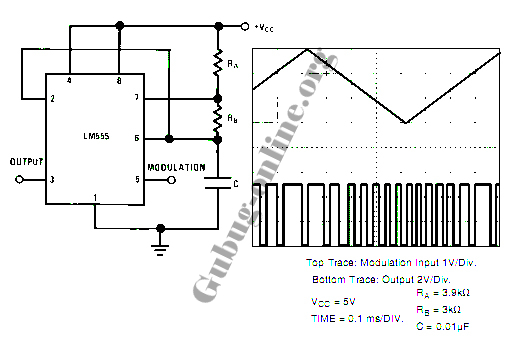
This design circuit for a pulse position modulator can be easily constructed using a 555 integrated circuit (IC). The pulse position modulator modulates the on-period while maintaining a fixed off-period. The circuit utilizes the 555 timer IC in astable mode...