
What transistor to use when building a simple MCU controlled LED blinking circuit

The circuit design involves a PIC12 microcontroller, which is a compact and efficient device suitable for controlling simple tasks such as LED blinking. The microcontroller will be programmed to generate distinct timing sequences for each of the three LEDs, allowing for varied blinking patterns.
The schematic will include the following components:
1. **Microcontroller (PIC12)**: The central processing unit that executes the blinking patterns. It will be powered by a suitable voltage source, typically 5V DC.
2. **LEDs**: Three individual light-emitting diodes, each connected to a different output pin of the PIC12. Resistors will be included in series with each LED to limit the current and prevent damage. The values of these resistors should be calculated based on the LED specifications and the supply voltage.
3. **Resistors**: Each LED will require a current-limiting resistor, calculated using Ohm's Law. For example, if an LED has a forward voltage of 2V and a desired current of 20mA, a resistor value of approximately 150 ohms would be appropriate when using a 5V supply.
4. **Programming Interface**: To load the blinking pattern program onto the PIC12, a programming interface (such as ICSP - In-Circuit Serial Programming) may be included in the schematic. This allows for easy updates to the microcontroller's firmware.
5. **Power Supply**: A stable power source will be required to ensure consistent operation of the microcontroller and LEDs. This can be a battery or a regulated power supply, providing the necessary voltage and current.
The blinking patterns for the LEDs can be programmed using a simple loop structure in the firmware. Different delays can be implemented to achieve various blinking effects, such as alternating flashes, simultaneous blinking, or sequential lighting.
Overall, this circuit provides a straightforward yet effective means of demonstrating microcontroller capabilities in controlling multiple outputs with varying behaviors. The design can be expanded or modified to include additional features such as user inputs or more complex patterns as needed.This is my conceptual schema to use a PIC12 to control the blinking of 3 LEDs with different blinking patterns. I have a few questions that would like to ask. 🔗 External reference
Related Circuits
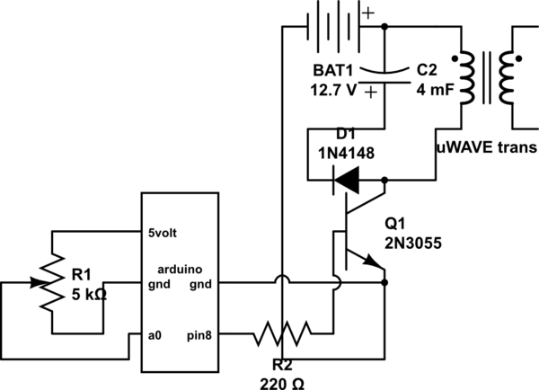
If both devices need to be powered from the battery, should the emitter be connected to the ground of the Arduino and the battery to prevent current from flowing through the Arduino ground, ensuring a clean pulse? Alternatively, can...

This circuit provides a simple visual indication of audio level signals, adaptable to various user requirements. It can be configured for different input levels, which can be adjusted using trimmer potentiometers TR1 (state) and TR2 (gain). The audio signals...
Electronics tutorial about the monostable multivibrator circuit, also known as a one-shot monostable multivibrator, used as a pulse generator circuit. The monostable multivibrator is a crucial component in electronic circuits, functioning as a pulse generator that produces a single output...

This infrared (IR) remote extender enhances the range of most basic IR remotes operating at a 40KHz modulation frequency significantly. When in operation, the remote is aimed at the detector on the circuit, and a button is pressed. The...

Figure 1-89 illustrates a loudness control circuit. A potentiometer is connected to ground, with 30% of the total resistance at the tap. When the slider arm is adjusted to the tap position, a midrange attenuation of 30 dB is...

Q1 functions as a Colpitts crystal oscillator. If the crystal being tested is operational, the RF signal is rectified by diodes D1 and D2, which activates Q2 and illuminates indicator LED2. Additionally, LED1 serves as a power indicator. The circuit...