
Bluish Flasher

The circuit design employs a blue LED and a white LED in conjunction to simulate the illumination effect of a camera flash. The blue LED is typically used to represent the initial burst of light, while the white LED provides a broader spectrum of illumination that mimics the main flash.
A power source, such as a battery, is connected to the LEDs through a current-limiting resistor to prevent excessive current flow, which could damage the LEDs. The resistor value can be calculated based on the forward voltage and current specifications of the LEDs.
To enhance the realism of the flash effect, a microcontroller can be integrated into the circuit. The microcontroller can be programmed to control the timing and intensity of the LEDs, allowing for a rapid sequence of illumination that resembles an actual camera flash. The blue LED can be turned on for a brief moment before the white LED activates, followed by a gradual dimming effect to replicate the natural decay of light.
Furthermore, the circuit may include a photodiode or light sensor to adjust the brightness of the LEDs based on ambient light conditions, ensuring that the imitation flash remains effective in various lighting environments.
Overall, this circuit design offers an innovative approach to simulating camera flash effects, making it suitable for applications in photography, lighting design, or educational demonstrations in electronics.Firstly, it demonstrates how the combination of a blue and a white LED can be used to give a realistic imitation of a camera flashlight. Secondly, the goo.. 🔗 External reference
Related Circuits

This circuit is designed to flash a high-brightness red LED (5000 mcd), making it suitable for use in fake car alarms or other devices intended to attract attention. The specific values of the components are not critical, allowing for...

This circuit is built around one of the most popular timer integrated circuits, the 555 timer. It will flash the LED on and off at regular intervals. From left to right, the two resistors and the capacitor set the...

This circuit utilizes three readily available 555 timer integrated circuits (ICs), all functioning as astable multivibrators. The first 555 timer has both an on period and an off period of 1 second. This IC regulates the on/off intervals of...

The concept of this cost-effective flashing LED indicator is straightforward: it utilizes a low-frequency oscillator to control two LEDs. This flashing LED indicator circuit is designed to provide a visual signal using two light-emitting diodes (LEDs) that alternate in illumination....
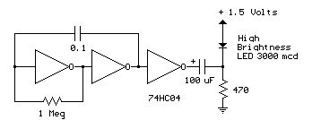
Several 1.5 V LED flasher circuits can be found online, and four of them are presented here. The flasher circuits operate on a single 1.5 V power supply. The design of a 1.5 V LED flasher circuit typically involves a...

The 8-lead plastic mini-DIP LM3909 integrated circuit was developed by National Semiconductor in the mid-1970s. It is a monolithic oscillator specifically designed to flash Light Emitting Diodes (LEDs). By utilizing the timing capacitor for voltage boosting, it can deliver...