
BMW R Series Motorcycle Regulator Schematic

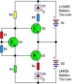
The described circuit involves a potentiometer (pot) that is used to adjust the voltage at its wiper, which is connected to a voltage source denoted as D+. The critical threshold for the operation of transistor Q1 is established by the relationship between the voltage at D+ and the voltage at the pot wiper (Vp). When the voltage at D+ exceeds certain levels, specifically when the difference (D+ - Vp) exceeds 7.6V, Q1 begins to conduct, indicating that the circuit is in an active state.
Transistor Q2 is influenced by the state of Q1 and is activated through resistor R5 when D+ falls below 13.7V. In this case, Q1 remains off, allowing Q2 to conduct, which in turn activates Q3. This cascading effect of transistors highlights a feedback mechanism that regulates the circuit's response based on the variations in D+.
The voltage across diode Df is also a significant parameter in this circuit. As D+ increases, Q1 starts to conduct, which causes a gradual decrease in the conduction of Q2 and Q3. This interaction results in a drop in the voltage across Df, indicating a dynamic adjustment in the circuit's operation based on the input voltage level at D+.
The overall design showcases a voltage regulation or control circuit that utilizes the properties of transistors and resistors to manage the flow of current and voltage levels effectively. Proper adjustment of the potentiometer is essential for ensuring that the circuit operates within the desired parameters, particularly in applications where voltage thresholds are critical for performance.Correctly adjusted, the voltage on the pot wiper is slightly less than half D+ (appx. 0.47*D+) and Q1 will conduct if (D+)-(Vp)>6.2+0.7+0.7, or 0.53*(D+) > 7.6V, (D+) > 14.3V. If D+ is lower than 13.7V, Q1 will not conduct, Q2 will get driven via R5, and Q3 will conduct. Df will carry a voltage. When D+ rises, Q1 will start conducting, Q2 will get pinched gradually, and so will Q3. Voltage on Df will drop. 🔗 External reference
Related Circuits
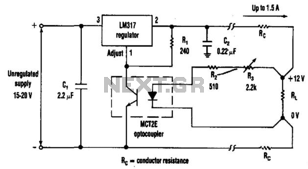
The optocoupler provides load sensing for a 3-terminal regulator, such as the LM317 series. Rl sets a current of 5 mA through the optocoupler transistor, and R3 is adjusted for 12 V across the load. The circuit utilizes an optocoupler...
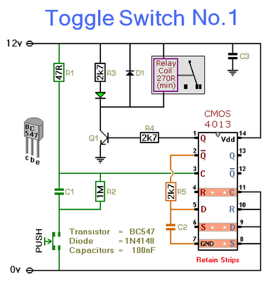
This circuit will activate and deactivate a relay with the press of a button. Any momentary push-to-make switch can be utilized. Pressing the button once will activate the relay, while pressing it a second time will deactivate the relay....
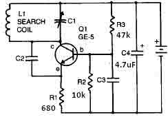
This metal detector circuit requires a power supply of 9 volts (DC) or a 9-volt battery. The circuit includes a variable capacitor C1 valued at 365 pF, a 100 pF silver mica capacitor C2, a 0.05 µF disc capacitor...
Each issue produces a specific frequency of sound, and the audio remote control will switch states based on these frequencies. The circuit is designed to detect other frequencies emitted by environmental sounds with strong anti-interference capabilities. The circuit operates...
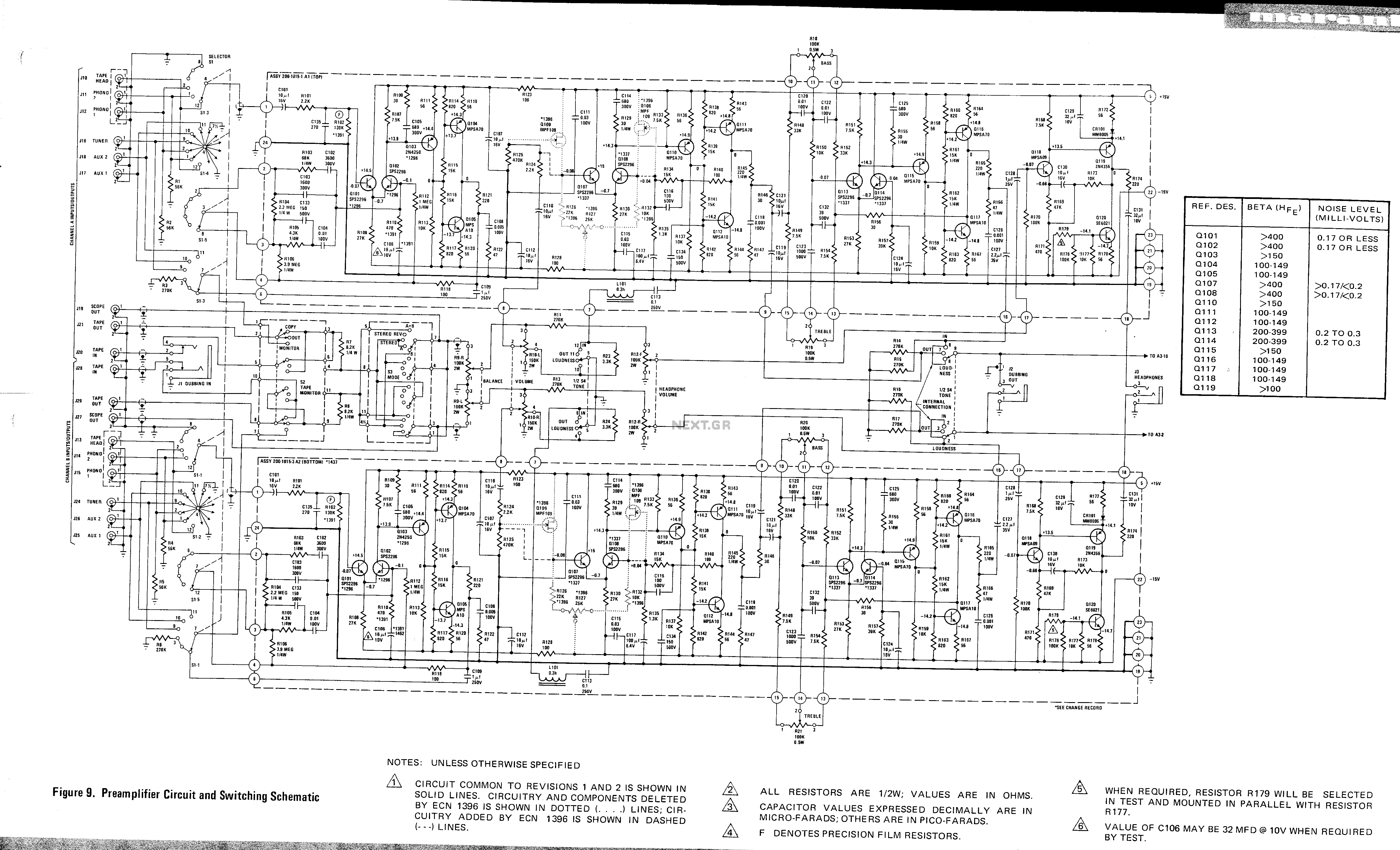
This is a preamplifier circuit and switching schematic for the Marantz Model 33. The Marantz Model 33 preamplifier circuit is designed to amplify low-level audio signals from various sources before sending them to a power amplifier. The schematic typically includes...
Most 24V power systems in trucks, 4WDs, RVs, boats, and similar applications utilize two series-connected 12V lead-acid batteries. The charging system is designed to maintain the total voltage of the two batteries. If one battery begins to fail, the...