
BMW40 Ibus tuner Amp Modification

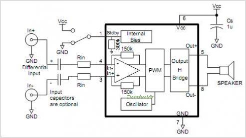
The described circuit functions as a non-inverting amplifier, which is designed to amplify an input voltage while maintaining its phase. This configuration is ideal for applications where a high input impedance and low output impedance are required. The non-inverting amplifier utilizes operational amplifiers (op-amps) to achieve the desired gain, which can be set by external resistors.
In this circuit, the gain (Av) is determined by the resistors connected to the op-amp, following the formula Av = 1 + (Rf/Rin), where Rf is the feedback resistor and Rin is the resistor connected to the input. This allows for precise control over the amplification level.
Following the amplification stage, a voltage follower or buffer stage is employed. This is typically implemented using another op-amp configured in a unity-gain configuration. The purpose of the buffer is to provide impedance matching between the high-impedance output of the amplifier and the load, which may have a lower impedance. The voltage follower ensures that the output voltage remains equal to the input voltage while providing the necessary current drive capability without affecting the performance of the preceding amplifier stage.
The entire circuit is powered by a dual power supply, providing both positive and negative voltage rails to the op-amps, which is essential for proper operation. Bypass capacitors are also included near the power supply pins of the op-amps to filter out any noise and ensure stable operation.
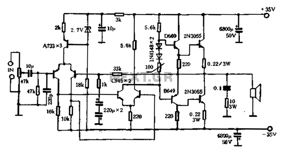
In summary, this circuit effectively amplifies an input voltage while maintaining integrity and providing the necessary impedance matching for subsequent stages or loads. It is commonly used in audio processing, sensor signal conditioning, and other applications requiring precise voltage amplification.How the circuit worksh1. Your title here The circuit comprises a non inverting amplifier with a final output buffer stage or voltage follower for impedance matchin.. 🔗 External reference
Related Circuits
This circuit is not easy to build, but it provides excellent audio quality. It serves as a high-quality preamplifier, capable of driving high-quality power amplifiers while delivering good sound. The described circuit functions as a high-fidelity audio preamplifier, designed to...
An active high-power tube operates in the MHz range, priced around 3 to 4 yuan, with a transition frequency (fT) exceeding one-fifth of 50 MHz for similar power tubes. This circuit is designed for high reliability in low-frequency high-power...
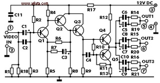
This electronic circuit is a video signal amplifier that provides a broad bandwidth amplifier with a capacity of 5 MHz. It is designed to take video signals from a VCR and amplify them adequately to drive up to three...
This amp uses the basic circuitry of the 60W power amp but modified for true Class-A operation. This amp has been built by several readers, and the reports I have received have been very positive. With simulations, everything appears...
Stationary - MOPLL & Silicon Tuner TUA6020 2 Band TV Tuner Mixer-Oscillator-PLL with balanced IF-Amplifier. The TUA6020 device integrates a digitally programmable Phase Locked Loop (PLL) with a mixer-oscillator block that includes two balanced mixers and oscillators suitable for...
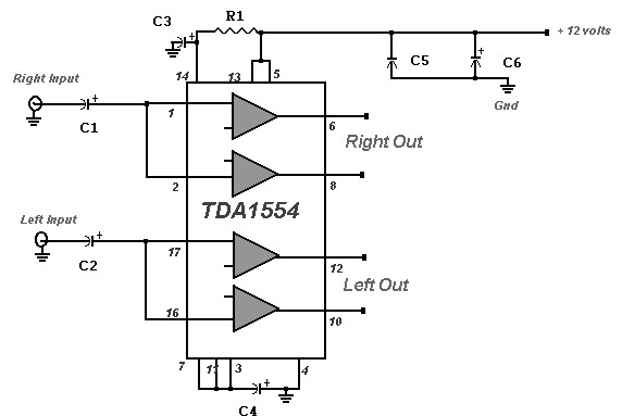
A 22 Watt stereo amplifier circuit diagram is presented. This circuit can be utilized for audio home amplifiers as well as car audio amplifiers. It features a straightforward design, is cost-effective, and is very easy to assemble, making it...