
22 Watt Stereo Amplifier

The 22 Watt stereo amplifier circuit employs the TDA1553 integrated circuit, which is designed for high-efficiency audio amplification. The TDA1553 is a Class-B amplifier, known for its ability to deliver quality sound output while minimizing distortion. The circuit typically includes a few passive components such as capacitors and resistors, which are essential for filtering and stability.
In the schematic, the input stage is connected to the audio source, such as a car stereo receiver. The amplifier's output is directly linked to the speakers, ensuring that the audio signal is amplified effectively. The circuit design should include decoupling capacitors to filter out any noise from the power supply, thereby enhancing the overall audio quality.
The use of the TDA2004 in conjunction with the TDA1553 allows for a robust amplification stage, capable of handling the demands of car audio systems. The TDA2004 serves as a secondary amplifier stage, providing additional power handling and output capabilities. It is important to incorporate proper heat dissipation methods, such as heatsinks, to prevent thermal overload during operation.
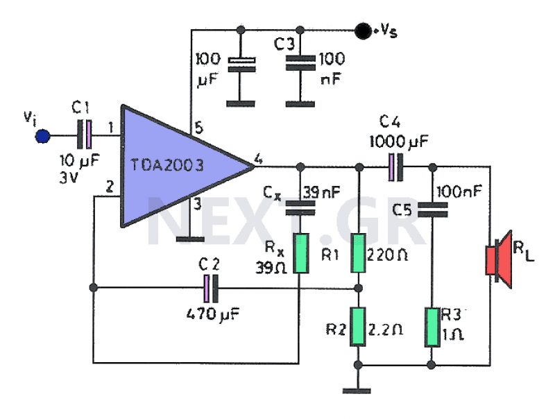
When assembling the circuit, attention must be paid to the orientation of the components and the connections to avoid short circuits. Additionally, ensuring that the speaker is isolated from the chassis ground is critical to prevent potential damage to the integrated circuits. This amplifier circuit is ideal for those seeking an affordable and efficient solution for enhancing audio performance in vehicles or home audio systems.22 Watt Stereo Amplifier circuit diagram. This circuit can be used for audio home amplifier and car audio amplifiers. It is extremely simple design, inexpensive and very easy to build. Even a newbie hobbyst will easy assemble this circuit. The scheme given here is a car stereo amplifier circuit can be used in That car or other vehicle. The circuit is basedTDA1553, which is aClass-Baudioamplifier. As you can see this circuitisverysimple, consisting onlyof theICand thecapacitor6. Here is a circuit diagram of car stereo. This 20w car audio amplifier circuit described hereoffers a20 wattboosterthatwillallow youtorealize thepower amplifierwith which one canincrease the poweroutputfromthe carstereoup to20Wattsmaximum. The inputINis connected to theoutputof thereceiver, Uoutputis connectedto the speakeras shownoncaraudioamplifierscheme.
It is veryimportanttoensurethat thespeakerhas no connection tothe chassis(ground)ifnot, the integrated circuitIC1, aTDA2004will. 🔗 External reference
Related Circuits
Often, a small amplifier is required to accommodate the needs of compact spaces. This amplifier can be configured as either mono or stereo, and its circuitry is capable of efficiently driving two small speakers. Constructing the amplifier necessitates only...
A stereo power amp designed for use in portable players and radios. A 3V supply can be used to drive headphones providing 20mW in 32 Ohms per channel. A 9V supply will provide 1W in 8 Ohm per channel...
The Audio Automatic Gain Control (AGC) circuit monitors the output signal level of an audio preamplifier. When the input signal increases, the AGC circuit automatically reduces the amplifier's gain. Conversely, when the input signal decreases, the AGC circuit increases...
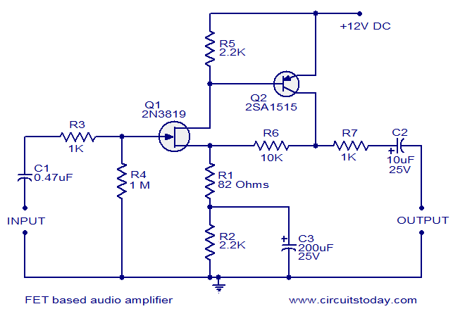
This circuit is a low-noise audio preamplifier that utilizes one FET and one BJT. The audio signal to be amplified is connected to the base of FET Q1 through capacitor C1 and resistor R3. The base of transistor Q2...

Sometimes referred to as the JFET µ-amp, this circuit offers a very low power, high gain amplification function. As the drain current decreases, the µ of a JFET increases, meaning that the lower the drain current, the greater the...
The YD9088 is a bipolar integrated circuit designed for use in mono portable and pocket radios. It is advantageous when minimizing peripheral components, which should be of small dimensions and low cost, is a priority. The circuit incorporates a...