
Boost Switching Converter Design Equations

In the design of a power converter, selecting the appropriate inductor is critical to achieving optimal performance and stability. The inductor not only influences the ripple current but also impacts the overall efficiency and response of the converter during varying load conditions. When designing a boost converter, it is essential to account for the characteristics of the inductor, such as its inductance value, saturation current, and RMS current rating. A larger inductor will generally result in a lower ripple current, which can enhance the stability of the output voltage. However, this must be balanced against the physical size and cost of the inductor, as larger inductors can lead to increased component costs and board space requirements.
The selection process should begin with determining the maximum load current and the desired output voltage ripple. From these parameters, the inductor value can be calculated using the formula derived from the converter's operation principles, taking into consideration the switching frequency and duty cycle. Next, the saturation current rating of the inductor must be verified to ensure it exceeds the peak current expected during operation. This peak current is influenced by the load conditions and the converter's duty cycle, which varies with input voltage and load changes.
Furthermore, the inductor's RMS current rating must be assessed to ensure it can handle the continuous current without overheating. This is particularly important in high-frequency applications, where core losses and copper losses can significantly affect efficiency.
In summary, careful consideration of the inductor's specifications, including inductance, saturation current, and RMS current rating, is essential in the design of a robust and efficient power converter. By ensuring that the inductor is appropriately sized for the application, stability issues can be minimized, leading to improved reliability and performance of the converter circuit.Where VD is the voltage drop across the diode, and VTrans is the voltage drop across the transistor. Note that the continuous/discontinuous boundary occurs when io is zero. The main question when designing a converter is what sort of inductor should be used. In most designs the input voltage, output voltage and load current are all dictated by the requirements of the design, whereas, the Inductance and ripple current are the only free parameters. It can be seen form Equation 1, that the inductance is inversely proportional to the ripple current. In other words, if you want to reduce the ripple, then use a larger inductor. Thus, in practice a ripple current is decided upon which will give a reasonable inductance. There are tradeoffs with low and high ripple current. Large ripple current means that the peak current is ipk greater, and the greater likelihood of saturation of the inductor, and more stress on the transistor.
So when choosing an inductor make sure that the saturation current of the inductor is greater than ipk. Likewise, the transistor should be able to handle peak current greater than ipk. The inductor should also be chosen such that the it can handle the appropriate rms current. It should be noted that when there is a light load the circuit can slip into discontinuous mode, where the inductor becomes fully discharged of it`s current each cycle.
When a load is reapplied the inductor needs to recharge, and so the transistor`s duty cycle increases pulling the inductor towards ground, and because of the increased duty cycle Vout decreases when we really want it to increase. This causes an instability, which is well known for boost converters, and not a problem with buck converters.
One way to combat this instability is to choose a large enough inductor so that the ripple current is greater than twice the minimum load current. When this condition is met then the inductor is always in continuous mode. Do you need help with an electronics design Daycounter provides contract electronics design services.
Contact us to give you a quote on your electronics design project. 🔗 External reference
Related Circuits
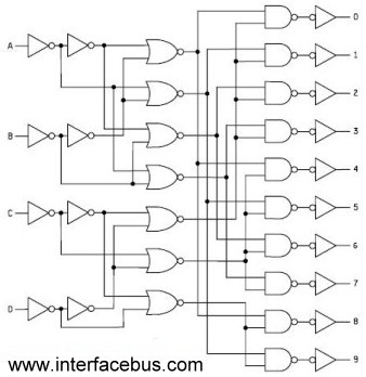
Binary Coded Decimal (BCD) is a number system that counts from 0 to 9 and then repeats. The table below illustrates the conversion between different numbering systems and BCD code. BCD is also known as 8421 because the least...

The current circuit is designed to convert sinusoidal input signals into TTL output signals. It is capable of handling input signals greater than 100 mV and operates effectively at frequencies up to approximately 80 MHz. Transistor T1 is configured...
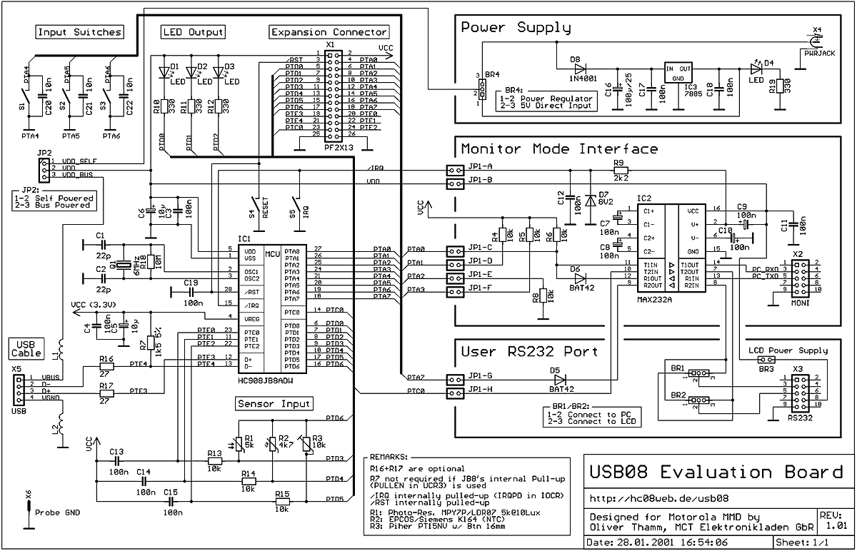
The primary target audience of the USB08 Reference Design consists of developers focused on microcontroller firmware and hardware, as well as those dealing with Windows driver and application software issues. USB (Universal Serial Bus) serves as a standardized bus...
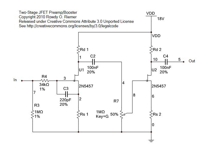
This circuit functions as a clean preamplifier or booster pedal. It is specifically designed for clean amplification rather than overdrive, although it can be overdriven to produce soft clipping typical of JFETs. The circuit originated as a booster pedal...
Electronic ballasts for dimming fluorescent lamps require a control interface for the user to set the desired lamp brightness level. Existing interface circuits include a 1-to-10 Vdc interface, a digitally-addressable lighting interface (DALI), triac-based wall dimmers, three-way lamp sockets,...
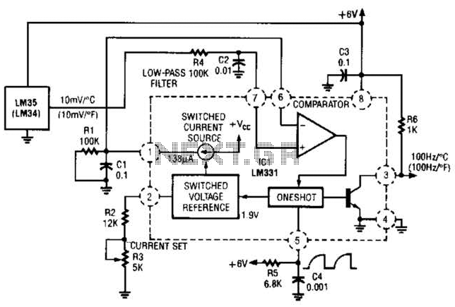
In this circuit, an LM34 or LM35 generates a frequency that is proportional to temperature. The reference current (138) is established through resistor R3. The output can be utilized to drive a display, frequency counter, or other indicating devices...