
bq51013 Receiver Circuit Restarts

The circuit utilizes the bq51013 EVM receiver as a wireless power receiver, which is designed to harvest energy from a compatible transmitter. The TPS61085 boost converter is employed to step up the voltage to the required level for the load. The issue arises when the load connected to the output exceeds the capability of the boost converter, leading to an overload condition. The continuous restart of the system indicates that the boost converter is unable to maintain stable operation under the specified load conditions.
To address the problem, it is essential to evaluate the power requirements of the load and the capability of the TPS61085 boost converter. The boost converter's data sheet should be consulted to determine its maximum output current and efficiency at the required output voltage. It may be necessary to consider a boost converter with a higher current rating or improve the thermal management of the existing converter to handle the increased load.
Testing the wireless power receiver with a resistive load provides insight into its performance independent of the boost converter. The successful operation at 850 mA indicates that the receiver is capable of delivering power without issues when not coupled with the boost converter. This suggests that the problem likely lies within the boost converter's ability to handle the load rather than the receiver's output.
Further investigation should include measuring the input voltage to the boost converter during operation to ensure it remains within the acceptable range. If the input voltage drops significantly under load, it may indicate that the receiver is not supplying sufficient power, which could lead to instability in the boost converter. Additionally, verifying the connections and components within the circuit for any signs of damage or improper configuration is crucial.
In conclusion, the circuit's inability to deliver the required load current appears to stem from the limitations of the TPS61085 boost converter under the specified load conditions. Careful analysis of the circuit components and power requirements, along with potential adjustments or replacements, will be necessary to resolve the issue.I have built several boards using the bq51013 EVM receiver circuit and a TPS61085 boost converter circuit(designed in SwitcherPRO Design Software) to increase the voltage level to 5. 7Volts. The problem that is that when a load of 580mA(required by end application of the circuit) is connected the system begins to restart again and again and continue
s as long as the load is attached. the boost converter draws 780mA of current during this state. What could be the possible reason for the circuit for not being able to deliver the required load current. And how can it be fixed. Schematic of the circuit(W C R. jpg) has been attached for reference. To narrow the problem down I would recommend disconnecting the boost converter and test the wireless power 5V RX with a resistive load to determine if it can provide 1.
0A at 5V without problems. The boost converter was disconnected and then a resistive load of 850mA was connected to the 5V output of the receiver, it worked just fine. The maximum current which boost drains at start-up was recorded at 800mA. Also since the receiver chip has current limit function so it will limit the current when pulled beyond its limit setting, it should not shutdown or should it Yes ”the RX will communicate with the TX using load modulation and changes in the output load look the same.
But the TX only has to receive a valid communication packet every 1. 2sec to continue power transfer. The packets are sent every 250mS. All content and materials on this site are provided "as is". TI and its respective suppliers and providers of content make no representations about the suitability of these materials for any purpose and disclaim all warranties and conditions with regard to these materials, including but not limited to all implied warranties and conditions of merchantability, fitness for a particular purpose, title and non-infringement of any third party intellectual property right. TI and its respective suppliers and providers of content make no representations about the suitability of these materials for any purpose and disclaim all warranties and conditions with respect to these materials.
No license, either express or implied, by estoppel or otherwise, is granted by TI. Use of the information on this site may require a license from a third party, or a license from TI. Content on this site may contain or be subject to specific guidelines or limitations on use. All postings and use of the content on this site are subject to the Terms of Use of the site; third parties using this content agree to abide by any limitations or guidelines and to comply with the Terms of Use of this site. TI, its suppliers and providers of content reserve the right to make corrections, deletions, modifications, enhancements, improvements and other changes to the content and materials, its products, programs and services at any time or to move or discontinue any content, products, programs, or services without notice.
🔗 External reference
Related Circuits
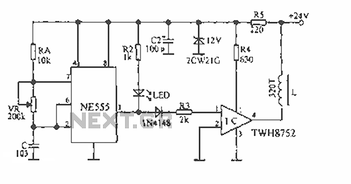
The circuit consists of two 555 timer oscillators configured in a dual timer arrangement, both set up in astable mode. Components include a 1N4148 diode and a 555 integrated circuit. The dual 555 timer circuit operates in astable mode, generating...
The device is designed to accelerate the defrosting process of fish, meat, and other foods by utilizing audio vibrations. This method allows for defrosting in warm water, significantly reducing the time required compared to conventional methods, while preserving the...
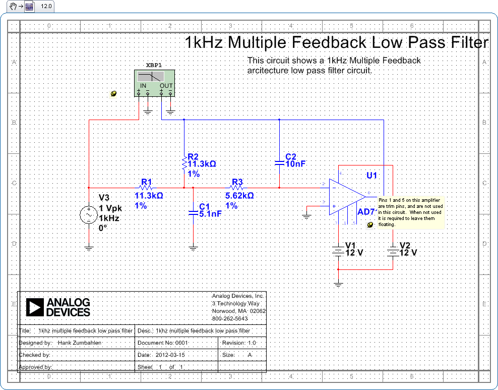
Pins 1 and 5 on this amplifier are trim pins and are not utilized in the circuit. When not in use, it is necessary to leave them floating. In electronic amplifier circuits, trim pins are often included for calibration or...
This circuit was built to charge two series lithium cells (3.6 volts each, 1 Amp Hour capacity) installed in a portable transistor radio. The circuit is designed to efficiently charge two lithium-ion cells connected in series. Each cell has a...
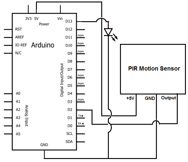
Once the motion sensor detects motion, the Arduino can be programmed to activate an LED, turn on a motor, sound a buzzer, etc. In this circuit, for simplicity, an LED will be turned on when the motion sensor detects...
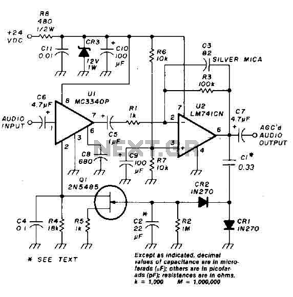
An audio signal applied to the input VI is passed through the operational amplifier 741, designated as U2. After amplification, the output signal V2 is sampled and sent to a negative voltage doubler/rectifier circuit composed of diodes CR1 and...