
1khz multiple feedback low pass filter circuit

In electronic amplifier circuits, trim pins are often included for calibration or adjustment purposes, but they may not always be necessary for the amplifier's operation. In this case, pins 1 and 5 are designated as trim pins, indicating that they serve no function in the current configuration of the circuit. It is essential to ensure that these pins remain unconnected or "floating" to prevent any unintended effects on the amplifier's performance.
Floating these pins means that they should not be connected to ground or any voltage source, as this can introduce noise or instability in the amplifier's operation. Proper handling of unused pins is crucial in maintaining the integrity of the circuit and ensuring optimal performance.
When designing or implementing this amplifier circuit, attention must be paid to the layout and connections to avoid accidentally connecting these trim pins to other circuit elements. Careful documentation and adherence to the schematic will facilitate correct assembly and operation of the amplifier, ensuring that it functions as intended without interference from unused components.Pins 1 and 5 on this amplifier are trim pins and are not used in the circuit. When not used it is required to leave them floating. 🔗 External reference
Related Circuits
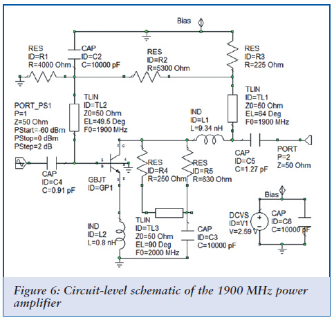
Achieving optimal performance from circuits used in third- and fourth-generation wireless systems necessitates tighter integration of previously separate tools. A degree of software synergy is crucial when designing circuits for modern wireless systems that utilize advanced modulation techniques alongside...
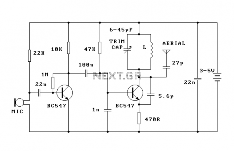
This FM transmitter (FM Tx) is about the simplest and most basic FM Tx it is possible to build and have a useful transmitting range. It is surprisingly powerful despite its small component count and 3V operating voltage. It...
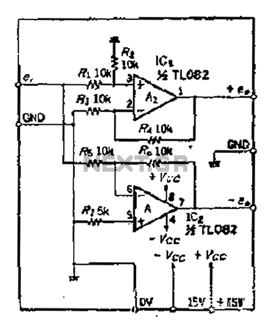
A balanced output is often associated with the positive phase amplifier output terminal of an operational amplifier, which is typically viewed as the inverting amplifier circuit. However, the reversed phase output can lead to a loss of balance in...
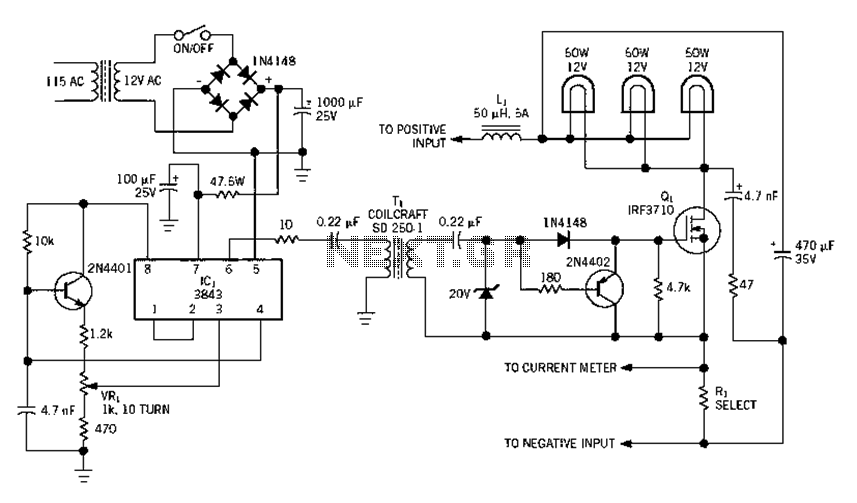
Electrical equipment provided for a power supply circuit design in the power section, as illustrated below. The power supply circuit design is a critical component in various electronic systems, serving as the backbone for powering other devices. The schematic typically...
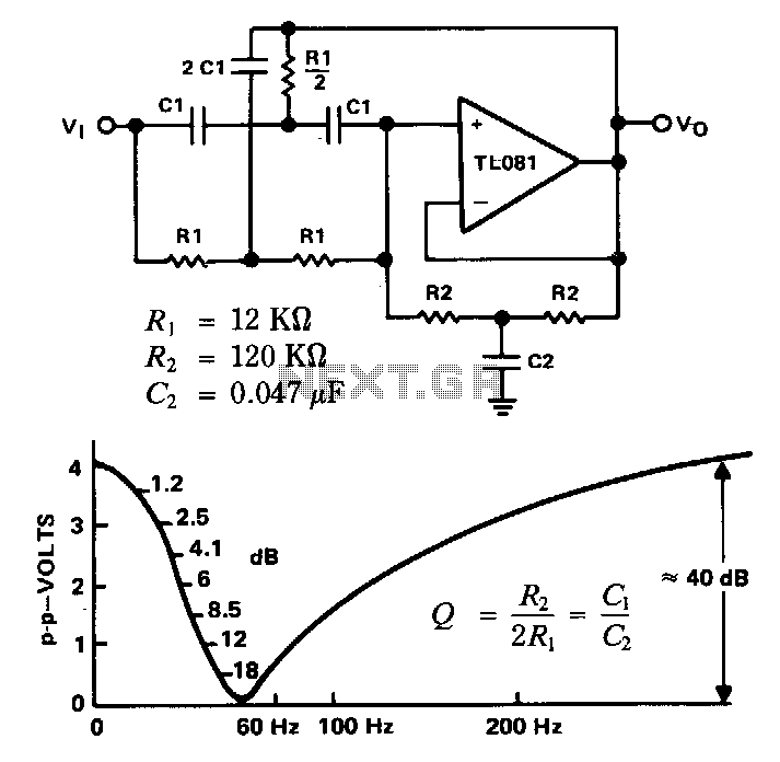
This filter is utilized to reject or block a specific frequency or range of frequencies. Such filters are commonly integrated into audio and instrumentation systems to eliminate a single frequency, for instance, 60 Hz. Commercial-grade components with a tolerance...
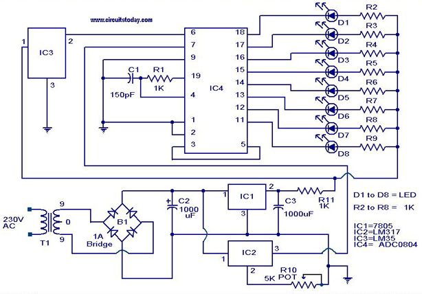
A digital temperature sensor circuit is explained with a circuit diagram. ICs ADC 0804, LM35, and LM317 are used in this digital circuit project. The digital temperature sensor circuit utilizes three primary integrated circuits (ICs): the ADC 0804, LM35, and...