
Breaker control signal circuit manually

The CS2 type manually operated breaker mechanism is an essential component in electrical systems that require reliable operation and control. This mechanism is designed to facilitate the manual interruption and restoration of electrical circuits, ensuring safety and functionality in various applications. The AC power operation allows for integration into alternating current systems, making it versatile for different environments.
The control signal circuit, as illustrated in Figure 6-68, incorporates several key elements that work together to manage the operation of the breaker. The 'wc' component serves as the control signal for a small signal bus, enabling communication and control over the circuit's operation. The auxiliary contacts, represented by 'QF', play a crucial role in providing feedback and ensuring the proper functioning of the circuit breaker during operation.
The 'YR' component refers to a temporary trip coil, which is activated under specific conditions to interrupt the circuit, protecting against overloads or faults. This feature is vital for maintaining system integrity and preventing damage to connected equipment. The 'QM' component consists of auxiliary contacts associated with the manual operating mechanism, allowing operators to manually engage or disengage the breaker as needed.
Indicator lights are also integral to the operation of the CS2 mechanism. The 'Hi' green indicator light signals that the system is in a normal operational state, while the 'H2' red indicator light serves as a warning that the circuit is in a trip condition or requires attention. These visual indicators provide immediate feedback to operators regarding the status of the breaker.
Furthermore, the circuit employs current limiting resistors, denoted as 'Ri' and 'R2', which are essential for managing the flow of electrical current within the circuit. These resistors help prevent excessive current that could lead to overheating or failure of components, thereby enhancing the overall reliability of the system.
In summary, the CS2 type manually operated breaker mechanism is a sophisticated assembly designed for effective control and protection of AC power systems, featuring a range of components that ensure safe operation and clear communication of circuit status. The integration of auxiliary contacts, trip coils, indicator lights, and current limiting resistors contributes to its robust functionality in various electrical applications. Breaker manually operated mechanism widely used type CS2. AC power operation manual operation control signal circuit shown in Figure 6-68. Figure, wc for the control of small b uses; ws small signal bus; QF circuit breaker auxiliary contacts; YR Temporarily trip coil (trip); QM manual operating mechanism auxiliary contacts; Hi green indicator light; H2 is red indicates can; Ri, R2 current limiting resistor.
Related Circuits
Figure 2-33 (a) illustrates the schematic diagram of a robot approaching an object. When no objects are detected in front of the robot, it moves forward in a straight line. If an object is detected on the left or...
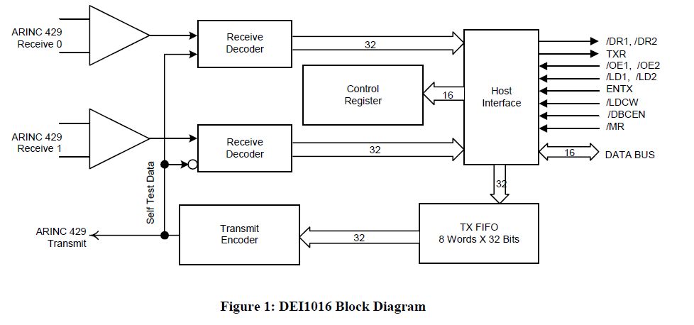
This document outlines the process of interfacing an Arduino with an ARINC 429 transceiver, illustrating the general methodology for connecting an Arduino to electronic circuits that can be applied to individual designs. The ARINC 429 bus is the predominant...
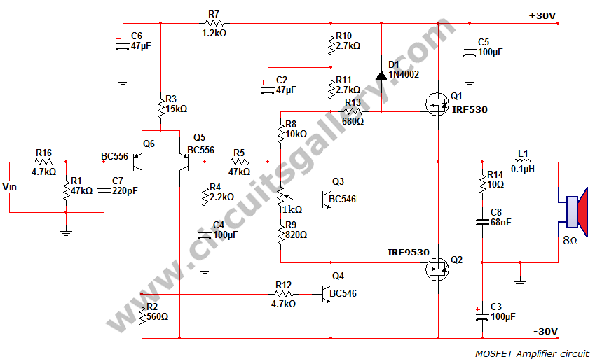
This is a MOSFET transistor-based power amplifier circuit that operates within a voltage range of +35V to -35V. The input voltage is pre-filtered and pre-amplified before being applied to the MOSFET switch. The pre-audio amplifier consists of a differential...
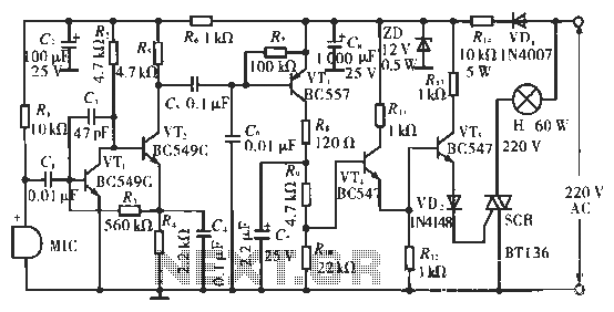
The circuit utilizes condenser microphones to detect sound and convert it into signal variations. This signal is then processed through directly coupled transistors VT1 and VT2, which form an amplification stage before being fed into a switching circuit. The...
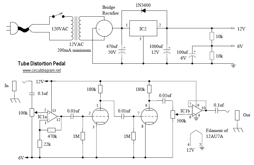
Tube distortion pedal circuit diagram. IC1: 747 dual op-amp; other ICs may be substituted, but the pinout will differ, so the datasheet should be checked. IC2: LM340K-12V voltage regulator. All resistors are 1/2 W. The bridge rectifier is a...
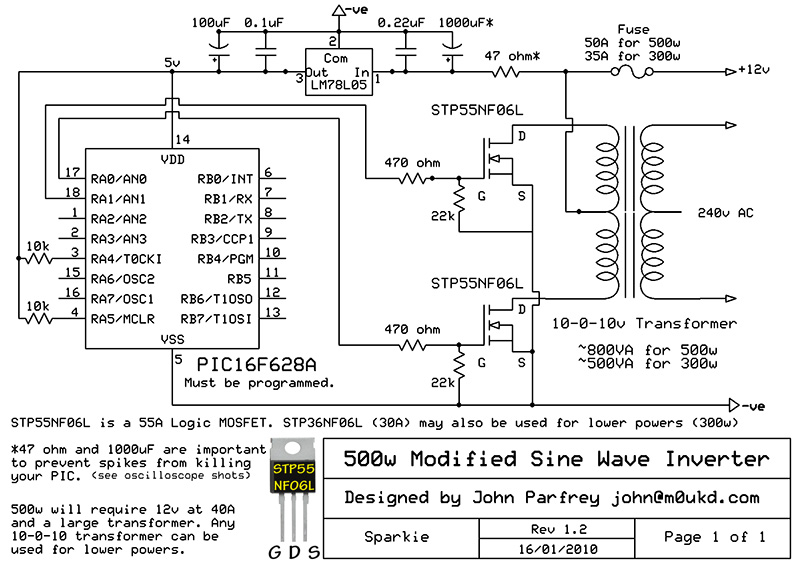
PIC controlled 500W Modified Sine Wave Inverter. The PIC16F628A is programmed to produce a logic 5V signal for 5ms at pin 17, followed by 15ms off. The described circuit implements a 500W modified sine wave inverter controlled by a PIC16F628A...