
PIC controlled 500W Modified Sine Wave Inverter

The described circuit implements a 500W modified sine wave inverter controlled by a PIC16F628A microcontroller. The primary function of the inverter is to convert DC voltage into a modified AC output suitable for powering various devices. The PIC16F628A microcontroller is programmed to generate a control signal at pin 17, which operates at a logic level of 5V. This signal is activated for a duration of 5 milliseconds, followed by a 15-millisecond off period, creating a pulsed output that is essential for the modulation of the inverter's output waveform.
The inverter circuit typically includes several key components: a DC power source (such as a battery), a power stage that may consist of MOSFETs or IGBTs to switch the DC input, and a transformer to step up the voltage to the desired AC level. The output waveform is modified to approximate a sine wave, which is more suitable for powering inductive loads compared to a pure square wave.
In addition to the microcontroller, the circuit may incorporate feedback mechanisms to monitor output voltage and current, ensuring stable operation and protection against overload conditions. The use of appropriate filtering components, such as capacitors and inductors, is critical to smooth the output waveform and reduce harmonic distortion.
Overall, the design emphasizes efficiency and reliability, making it suitable for various applications, including powering household appliances, tools, and other electronic devices that require a modified sine wave input.PIC controlled 500W `Modified Sine Wave` Inverter. The PIC16F628A is programmed to produce a logic 5v signal for 5ms at pin 17 then 15ms off.. 🔗 External reference
Related Circuits
The RF engineer sometimes needs an instrument that can reliably and quickly test a low-frequency quartz crystal unit. Finding such equipment can be challenging, and engineers often refer to electronic circuit handbooks for schematics that can perform this task....
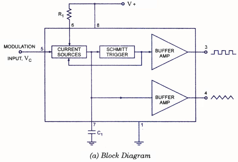
A voltage-controlled oscillator (VCO) is a type of oscillator in which the frequency of output oscillations can be adjusted by varying the amplitude of an input voltage signal. VCOs are commonly utilized in frequency modulation (FM), pulse modulation (PM),...
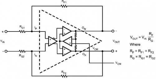
This circuit functions to provide balanced, low distortion amplification and level shifting for wide bandwidth differential signals. It utilizes the LMH6552 integrated circuit (IC) along with resistors. The LMH6552 is a high-speed, low-distortion amplifier designed for differential signal processing. It...
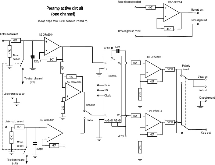
This document serves as a compilation of design notes, providing practical details as construction progresses, along with some photographs that will be included in due course. Currently, it functions as a progress report, blending immediate plans with actual construction,...

The DPT Transmitter is a dual-powered voice transmitter designed to operate in two modes: a high-power mode for long-range transmission and a low-power mode for extended battery life. It functions at a low power level of 100 mW and...
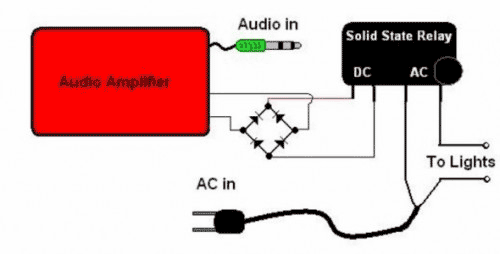
The basic Idea was to have Christmas lights flash with the music. In my design I use an ordinary amplified computer speaker, a diode bridge, and a ‘CRYDOM’ SSR (Solid State Relay). In order to increase the time that...