
Robot control circuit composed of transistor and NE555

The schematic diagram depicted in Figure 2-33 (a) outlines the operational mechanism of a robot designed for object detection and navigation. The primary function of this robot is to maintain forward motion until an obstacle is detected. The robot is equipped with sensors, typically ultrasonic or infrared, positioned at the front and sides to detect the presence of objects within its path.
When the sensors at the front of the robot do not detect any objects, the control system maintains a command for the motors to drive the robot forward. This movement is achieved through a differential drive mechanism, where two independent motors control the left and right wheels, allowing for precise movement and turning capabilities.
In scenarios where an object is detected on either side, the control system processes the sensor data to determine the appropriate response. If an object is detected on the left, the robot will initiate a right turn, and conversely, if an object is detected on the right, the robot will turn left. The turning action is executed by adjusting the speed of the motors; the motor on the side opposite to the detected object will slow down or stop, while the motor on the side of the detected object will continue to propel the robot forward, facilitating a smooth turn towards the object.
Figure 2-33 (b) provides a block diagram that outlines the control logic and signal flow within the robot's navigation system. This block diagram typically includes components such as the sensor inputs, microcontroller, motor drivers, and feedback loops that ensure the robot reacts appropriately to its environment. The microcontroller processes the input signals from the sensors, executes the control algorithms, and sends commands to the motor drivers to adjust the robot's movement accordingly.
Overall, the described system allows for efficient navigation and object interaction, enabling the robot to adapt its path based on real-time environmental feedback.Figure 2-33 (a) is the action schematic diagram of the robot closing to the object. When there is no objects in front of the robot, it will go forward in the straight line; when there is an object in left or right side of the robot,it will turn left or right to close to the object. Figure 2-33 (b) is the block diagram to achieve this action. Figure 2-33 (c).. 🔗 External reference
Related Circuits
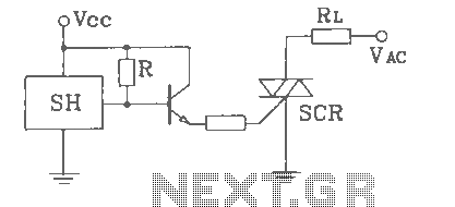
SH Hall opened with a double silicon output interface circuit The SH Hall sensor circuit is designed to provide a dual silicon output interface, which enables enhanced signal processing capabilities. This circuit typically integrates a Hall effect sensor that detects...
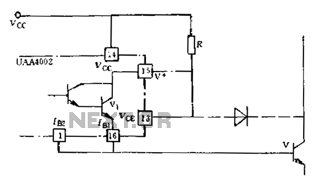
Anti-saturation devices have been removed from the UAA4002 routine applications. The base current of the switching transistor, which is driven by another transistor, is automatically adjusted. This adjustment allows the power transistors to operate in critical saturation. However, when...
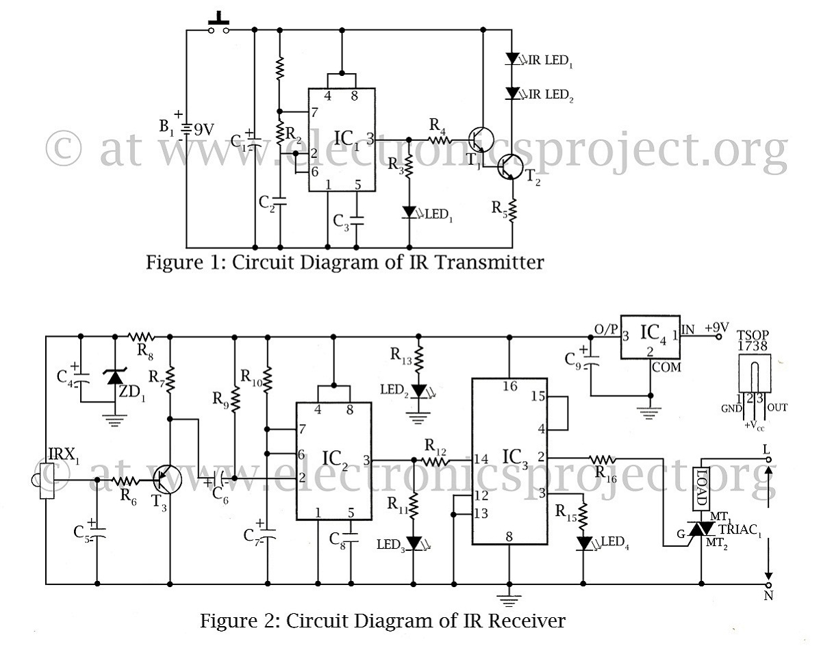
The infrared remote-controlled switch is the second remote-controlled project on this website, utilizing a 555 IC circuit diagram along with a description of the remote-controlled switch. The infrared remote-controlled switch operates using a 555 timer integrated circuit (IC), which is...
The SC41343 is designed as a type of infrared, ultrasonic, or RF remote control launch coding circuit. The internal circuit comprises a sequence generator, control logic circuit, 4-bit shift register, data extraction circuit, and latch circuit. Features include the...
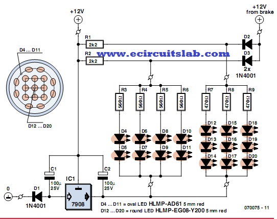
LEDs are increasingly utilized in motor vehicles, replacing traditional incandescent lamps due to their superior energy efficiency and extended lifespan. This article outlines a straightforward LED tail light specifically designed for motorcycles, scooters, and mopeds. There is a notable...
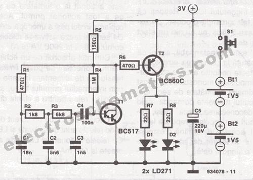
This infrared transmitter is designed for use with an infrared receiver. It operates using either two 1.5V batteries or a 3V lithium battery, allowing for a compact infrared communication system. The infrared transmitter circuit typically consists of an infrared LED,...