
battery monitor circuit

The battery monitor circuit serves as an effective solution for continuously monitoring the voltage levels of 12V lead-acid batteries, providing a visual representation through the use of LEDs. The LM3914 IC is a voltage level indicator that can drive multiple LEDs in a bar graph or dot mode, making it suitable for applications requiring voltage visualization.
In this configuration, the circuit is designed to accommodate a voltage range that corresponds to the typical operating levels of 12V lead-acid batteries. The use of a digital voltmeter during setup is crucial for precise calibration. By connecting the voltmeter to the designated pins of the LM3914, the user can ensure that the voltage reference is accurately set to 1.2 volts, establishing a baseline for the LED indicators.
The variable resistors VR1 and VR3 are used to fine-tune the sensitivity and response of the circuit. Setting these resistors to their center positions allows for a balanced calibration, ensuring that the LED indicators respond appropriately across the desired voltage range. The span adjustment of VR1 to equal 4.5 volts is essential for ensuring that the full scale of the LED indicators corresponds accurately to the voltage levels being monitored.
The resulting circuit can provide real-time feedback on the state of the battery, alerting users to potential issues such as over-discharge or under-voltage conditions, which can be detrimental to lead-acid batteries. This monitoring solution is particularly useful in automotive applications, where maintaining battery health is critical for vehicle performance and reliability. Additionally, the circuit can be adapted for use in other applications requiring similar voltage monitoring, making it a versatile tool for electronics engineers and hobbyists alike.Here is a battery monitor circuit which can be used to monitor the voltage of 12V lead acid batteries such as car batteries. The circuit is built around the LM3914 IC and some external components with 10 LEDs which will indicate the voltage level.
Two equipment are required for adjusting the circuit for 12 volt battery, one is lab power supply and second is digital volt meter. First you have to connect the digital volt meter to the pin 4 and pin 6 of the IC and adjust the variable resistor VR2 for a reading of 1. 2 volts and make VR1 and VR3 on their center settings now if the span between VR1 ends equal to 4. 5V then the circuit is ready to use. 🔗 External reference
Related Circuits

Many antique radios operate on batteries, including tube portables like the Zenith model K-401 and "farm" radios used in rural areas without electrical power. This article provides historical context on battery usage in early radios and offers guidance on...
This circuit is an automatic street light controller. The sensor used to detect changes in light is an LDR (Light Dependent Resistor). The working principle of the LDR is that when exposed to light, its resistance value decreases, while...
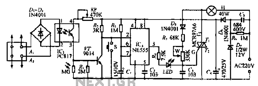
The Ai. A2 series operates with a telephone line, where sound anomalies or off-hook currents activate a light within an arc tube, which in turn triggers a photosensitive MOSFET. This process involves a saturated conduction base voltage that sends...
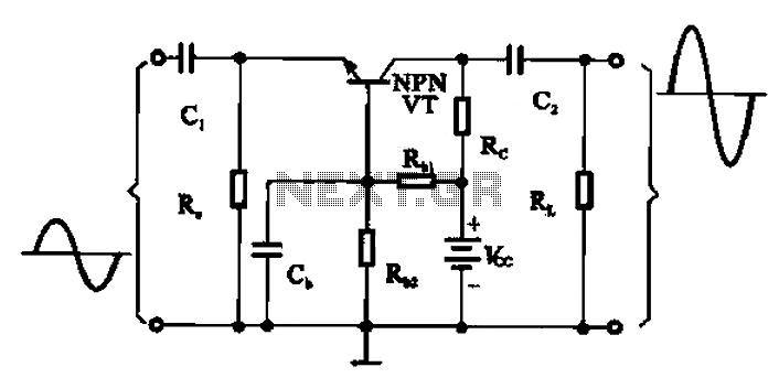
A common base transistor amplifier circuit is characterized by its basic structure, which includes key components such as a biasing resistor, capacitors for coupling, and an amplifying transistor. The circuit features four resistors that establish the quiescent point, with...
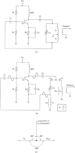
A widely recognized circuit is the Hartley oscillator, which is characterized by a tapped coil within the LC tank circuit. The tap point of the coil is grounded. The oscillator's amplifier section functions as a common-emitter amplifier, resulting in...
The wireless remote control transmitter circuit consists of control buttons S1 to S16, resistors R1 to R3, a capacitor C1, a regulator diode VS, a crystal oscillator BC1, and DTMF encoder integrated circuits IC1 and IC2. The circuit components...