
Brightness controller for low power lamps

The circuit employs the NE555 timer IC, which is a versatile component widely used in various applications. In this configuration, the NE555 operates as an astable multivibrator, generating a continuous square wave output. This output toggles between high and low states, with the duty cycle determining the proportion of time the output remains high. By adjusting the resistance of potentiometer R4, the duty cycle can be varied, which in turn modulates the average voltage applied to the load, resulting in a change in brightness for the incandescent lamp.
Transistor Q1 acts as a switch that controls the current flowing through the lamp. When the output of the NE555 is high, Q1 is turned on, allowing current to flow through the lamp, thus illuminating it. Conversely, when the output is low, Q1 turns off, cutting off the current and extinguishing the lamp. The effective brightness is directly proportional to the duty cycle; a higher duty cycle results in a brighter lamp, while a lower duty cycle leads to dimmer illumination.
This circuit's design can be easily adapted for other applications, such as controlling the speed of small DC motors. In this case, the same principles apply, where the average voltage delivered to the motor is controlled by adjusting the duty cycle of the NE555 output. By varying the duty cycle, the motor speed can be finely tuned, providing a practical solution for applications requiring speed control. Overall, this circuit exemplifies a straightforward yet effective method for managing the brightness of lamps and the speed of motors using minimal components.The circuit given here can be used to control the brightness of low power incandescent lamps. The circuit is based on IC NE555 which is wired as an astable multivibrator with variable duty cycle. The output of IC is connected to the base of transistor Q1. The Q1 drives the lamp. The duty cycle of the multivibrator can be varied by varying the POT R 4. As a result, the brightness of the lamp varies according to the position of the POT R4. The same circuit can be also used for speed control of small DC motors. 🔗 External reference
Related Circuits
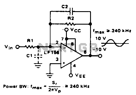
Parasitic input capacitance (ICi) is 3pF for LM5S, LF156, and LF157, along with any additional layout capacitance. This interacts with the feedback element and creates undesirable high-frequency effects. To mitigate this, a capacitor (C2) should be added in conjunction...
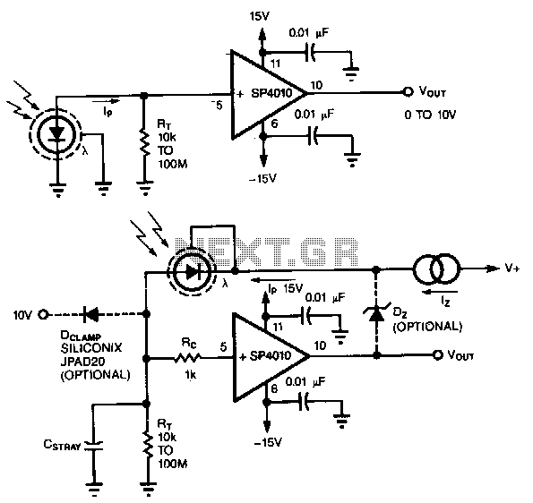
A common method of transforming the output current of a photodiode into a voltage signal involves paralleling the photodiode with a high-value load resistor, which results in a nonlinear response. Additionally, the combination of the load's transresistance, Rr, and...
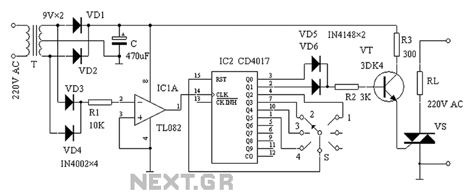
The zero-power regulator circuit is simple, reliable, and functional. It is suitable for various electric power adjustment applications, such as series-wound motor power adjustment. The operational principle of the circuit involves several components, including the power circuit, an AC...
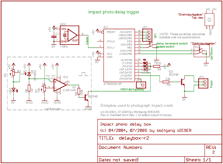
The objective is to capture various stages of a rapid process, especially in comparison to the resolution of the human eye. Due to the lack of advanced equipment such as a high-speed film camera, a practical setup utilizing a...
The circuit provides sufficient illumination suitable for reading purposes. Capacitor CX, in conjunction with diodes D1 through D4, constitutes the AC step-down circuit. CX lowers the high voltage AC from the mains to a low voltage AC, which is...
The first application has to be a stereo power amp, since that's what I built using two prototype modules. The reasons for this choice are twofold - a good high powered stereo amp is always useful, and it was important...