
BTL amplifier circuit composed by M51516L IC

The BTL amplifier configuration is designed to drive a load without requiring a center tap on the output transformer, thus maximizing efficiency and power delivery. In this setup, each amplifier drives one side of the speaker load, effectively doubling the output voltage across the load compared to a single-ended configuration.
The circuit's power supply voltage of 13.2V is critical for achieving the specified output power of 12W. The choice of a 4-ohm speaker load is optimal for this application, as it allows the amplifier to deliver higher current, resulting in increased power output. The design should include appropriate filtering capacitors to smooth out the power supply voltage and decoupling capacitors near the amplifier ICs to reduce noise and enhance performance.
The integration of components such as resistors, capacitors, and feedback loops within the circuit is essential for stability and sound quality. The feedback mechanism ensures that the amplifier maintains linearity and minimizes distortion, which is crucial for high-fidelity audio applications.
Thermal management should also be considered in the design, as the amplifier will generate heat during operation. Adequate heatsinking and ventilation should be provided to maintain optimal operating temperatures and prevent thermal shutdown.
In conclusion, this BTL amplifier circuit is a compact and efficient solution for driving low-impedance speakers, making it suitable for various audio applications, including home theater systems and portable audio devices.Figure 1-44 is dedicated BTL amplifier circuit, containing two single amplifier, and has integrated the relevant elements in the circuit, so the connection is very simple. The circuit at 13, 2V power supply voltage, output 12W load speaker on 4n maximum power.
Related Circuits
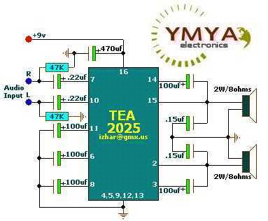
These circuits are based on TEA2025, a monolithic integrated audio amplifier in a 16-pin plastic dual in-line package manufactured by UTC. The circuit includes an internal thermal protector and is designed for portable cassette players and radios. It can...
You can play this game alone or with your friends. The circuit comprises a timer IC, two decade counters and a display driver along with a 7-segment display. The game is simple. As stated above, it is a scoring...
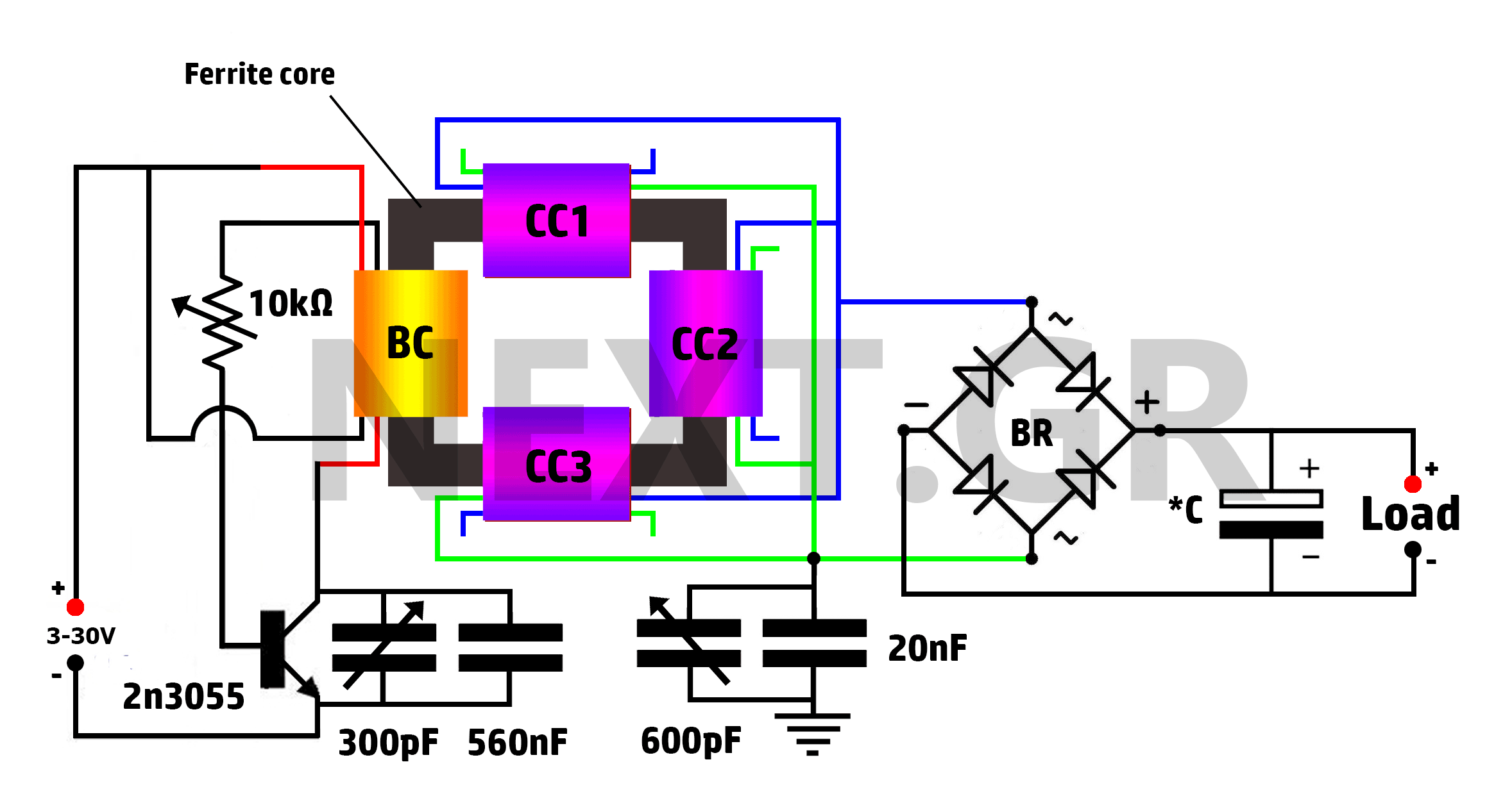
This is a Tesla/joule thief hybrid circuit that its inventor claims can produce 90 times the input power. The circuit can be self-looped and can provide 1050W of power, with only 11.6W looping back to supply the joule thief....

This is a sensor circuit designed for light detection. It utilizes the LM311 comparator and features a simple design. The comparator is powered by a 12 V DC supply and does not require a negative supply for efficient operation....
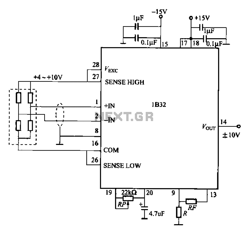
The circuit for bridge measurements is straightforward, as illustrated in the figure. The sensor bridge drive voltage can be adjusted between +4V and +10V, depending on the specific requirements of the sensor. Two fixed gain options of 333.3 and...
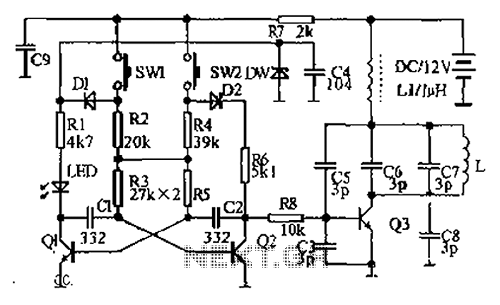
The circuit diagram illustrates a dual radio remote control switch system. The transmitter section features Q3, which generates a high-frequency carrier signal, while Q1 and Q2 form the oscillator circuit. Pressing switch SW1 results in an oscillation frequency of...