
Build A Digital Tachometer/RPM Counter Circuit

The Digital Tachometer/RPM Counter circuit is designed to measure the rotational speed of a shaft or wheel and display the results on a standard 16x2 character LCD. The core of this circuit is a microcontroller, specifically a PIC microcontroller, which processes the input signals and manages the output to the LCD.
The circuit operates by generating +5V pulses that are sent to the RC2/CCP1 pin of the PIC, where the capture module #1 is located. These pulses correspond to the number of rotations per minute (RPM) of the monitored object. The PIC is programmed to count these pulses over a specific time interval, allowing it to calculate the RPM based on the frequency of the incoming pulses.
The LCD interfacing consists of an 8-bit data bus along with 3 control signals: Register Select (RS), Read/Write (R/W), and Enable (E). The PIC sends commands and data to the LCD through these lines, controlling what is displayed. The power, ground, and contrast adjustments are crucial for proper LCD operation, ensuring that the display is clear and readable.
The HD44780 controller is prevalent in many LCD applications and is well-documented, making it easier to implement and troubleshoot. The datasheet provides detailed information on the command set, timing diagrams, and electrical characteristics, enabling efficient integration into the tachometer circuit. This design allows for real-time monitoring of RPM, making it a valuable tool for various engineering applications.The circuit for the Digital Tachometer/RPM Counter tutorial consists of only a few devices. Wire them up according to the following circuit diagram. The PIC I`m using is on a demonstration board, which means the clock, power and ground pins are already wired up so I didn`t bother to include that on the schematic. This is the digital tachometer po rtion of circuit that will send +5v pulses to the RC2/CCP1 pin of the pic. The CCP module, specifically the capture module #1 on the PIC is located at this pin. This is the standard 16x2 character LCD and the interface consists of 8 bits of data, with 3 control signals. Power, Ground and Contrast are the last signals to wire up. The PIC sends commands to this 16x2 LCD over the control and data lines and the LCD does what it is told.
The HD44780 system that this LCD uses is standarized and the datasheet is widely available. 🔗 External reference
Related Circuits
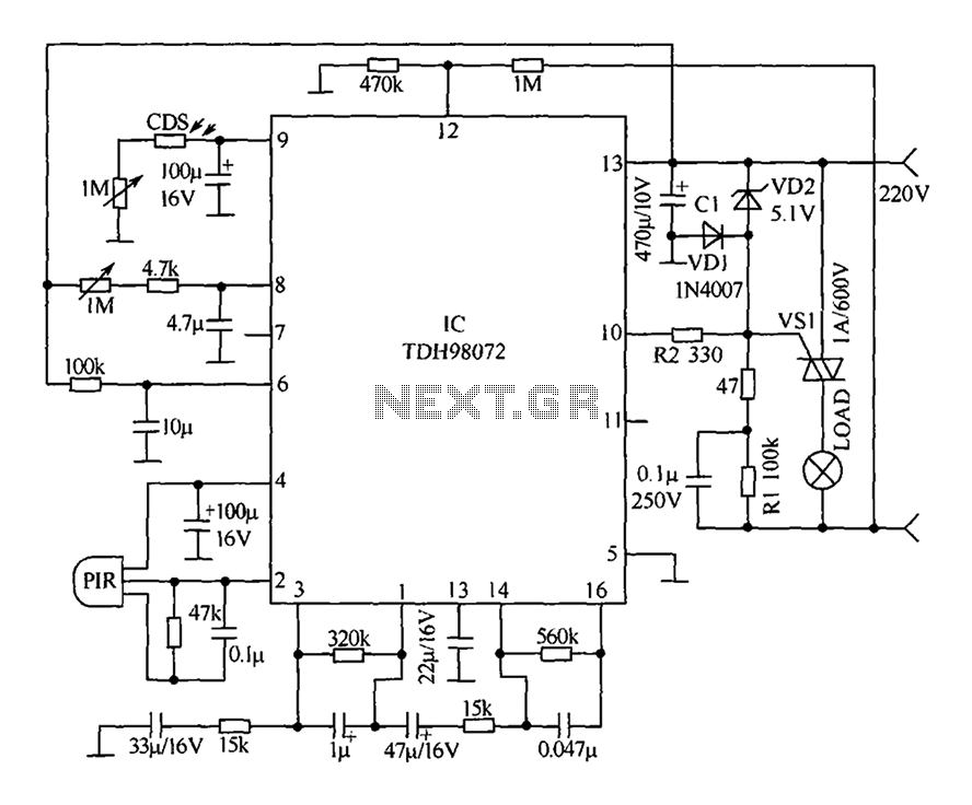
The circuit primarily consists of a new pyroelectric infrared sensor device, TDH98072, which features a special composition. This device is integrated with a control circuit characterized by simplicity, ease of adjustment, and high reliability. Additionally, the device can be...
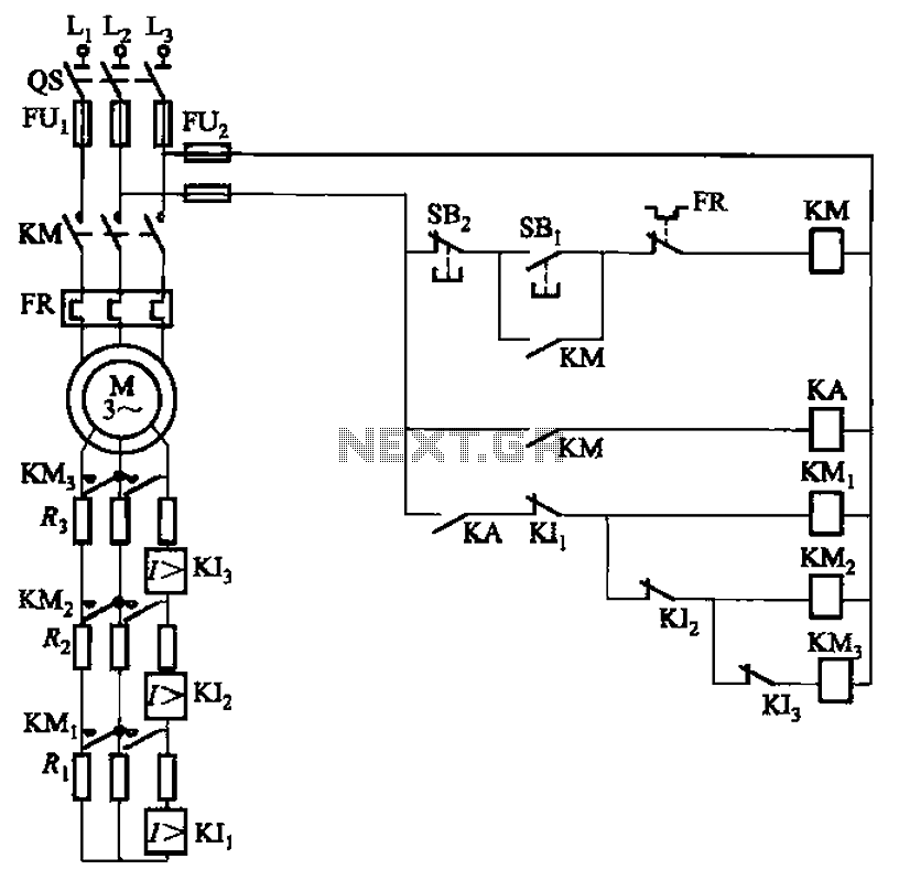
The circuit illustrated in Figure 3-161 features a first stage current detection mechanism utilizing a current relay (KI1) in series with a resistor (R1). The second stage employs another current relay (KI2) in series with a resistor (R2) for...
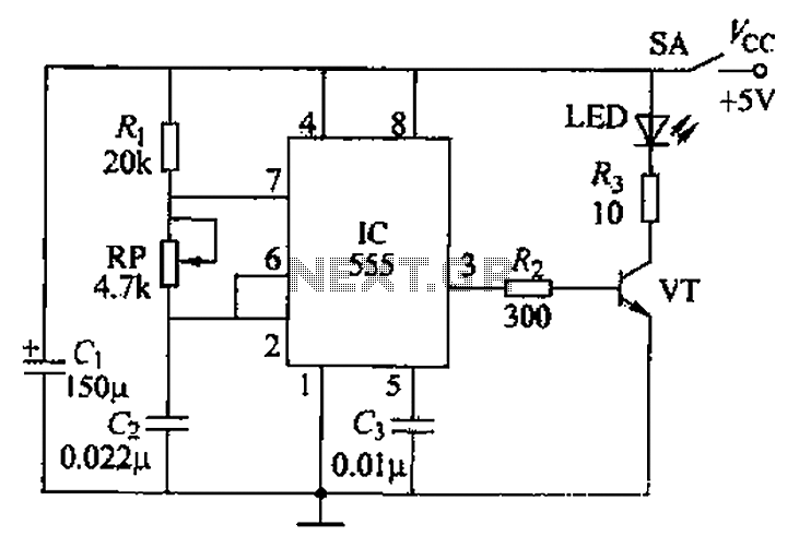
The circuit utilizes a 555 timer integrated circuit along with a transistor (VT) and several external components to create a multivibrator circuit. The charge and discharge time constants, Ti and T2, are defined, where Ti is approximately 0.7 times...
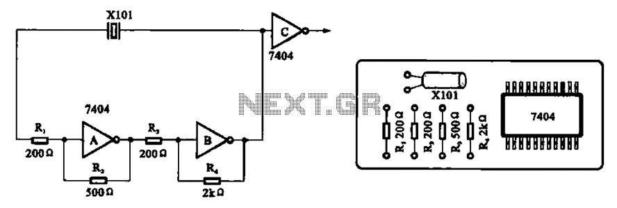
A clock oscillator is commonly utilized in digital signal processing circuits and microprocessor circuits. Digital signal transmission and signal processors necessitate a clock, which serves as the system's timing signal, while the data signal functions as a synchronization signal....
This circuit can manage nine independent telephones using a single telephone line pair located at nine different locations. It functions as a bidirectional telephone line simulator without the need for actual telephone lines, allowing for coupling, testing, and demonstration...
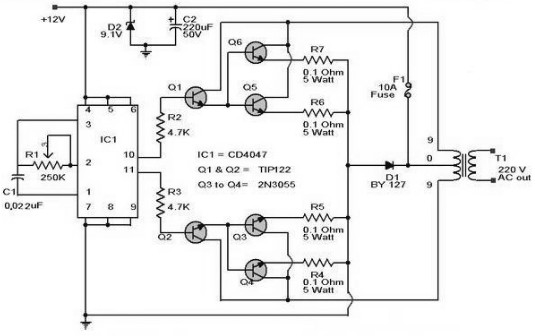
A 12 V car battery can be utilized as the 12 V input power source. The potentiometer R1 can be adjusted to achieve a 50 Hz output frequency. It is recommended to use a 10 A fuse in series...