
Three-start circuit current relay

The circuit design consists of three distinct stages, each utilizing a current relay for monitoring and controlling the current flow within the system. The first stage, featuring relay KI1 and resistor R1, is responsible for detecting the initial current level. When the current surpasses the specified threshold, the relay activates, allowing the current to flow to the subsequent stage.
In the second stage, relay KI2, in conjunction with resistor R2, serves as a secondary monitoring point. This relay is also designed to engage at a predetermined pull-in current, which is consistent with the first stage. However, it is important to note that each relay has a unique release current characteristic. KI2 will disengage at a higher current level compared to KI3, ensuring that the system maintains a specific operational threshold before allowing further current flow.
The third stage, represented by relay KI3 and resistor R3, acts as a final detection point. This relay is calibrated to respond to the lowest pull-in current of the three relays, ensuring that the system can handle lower current levels effectively. The differing release currents across the relays provide a layered approach to current management, allowing for fine-tuning of the circuit's response to varying load conditions.
Overall, the configuration of these relays and resistors creates a robust current detection system that can effectively manage and monitor electrical currents across multiple stages, ensuring reliable operation and protection of the connected circuitry. The careful selection of pull-in and release currents for each relay enhances the circuit's ability to respond dynamically to changes in current flow, thereby improving the overall efficiency and safety of the electronic system. Circuit shown in Figure 3-161. Figure, the first stage starting current detection by the current relay KIi Ri in series with the second stage starting current relay KI2 detecte d by the current series with R2, current relay Kla third stage starting from the current series with R3 detection. They have the same pull current, but have different release current, which KI1 maximum, K2 followed, Kl [3 minimum.
Related Circuits
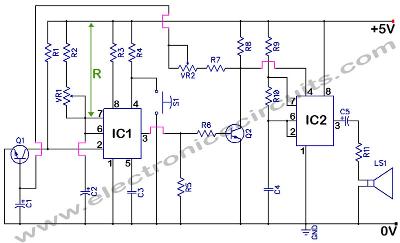
555 Timer with Audio Alarm Circuit. This circuit serves as a straightforward electronic timer equipped with an audio alarm feature. The 555 timer is a versatile integrated circuit widely used in various timer, delay, pulse generation, and oscillator applications. In...
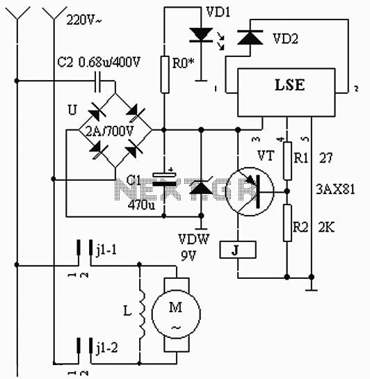
The circuit operates based on the interaction between an infrared light-emitting diode (VD1) and an infrared receiver diode (VD2). When VD1 emits infrared radiation, it is detected by VD2, which causes a decrease in its internal resistance. This change...
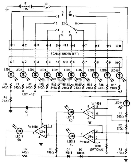
The cable tester utilizes two operational amplifiers (op-amps) configured as window comparators to detect short or open circuit conditions. A third op-amp comparator is employed to indicate a properly functioning circuit, meaning it is neither open nor shorted. Colored...

The Quick and Easy Wireless circuit is not overly complex, but it requires careful verification of connections before initial operation. Key components in the circuit include the 7805 voltage regulator, the 18F452 microcontroller, an RC Receiver, and an RC...
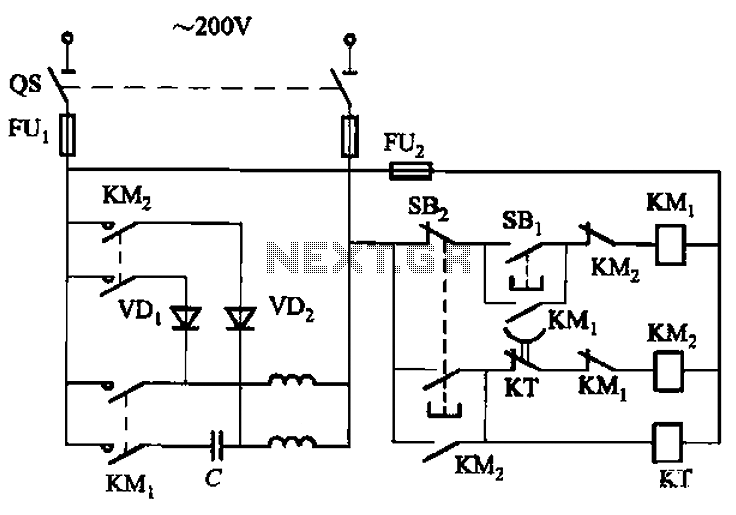
The circuit depicted in Figure 3-150 involves a contactor (KM1) that releases when the system is shut down. The contactor KM2 is energized, allowing a 220V AC power supply to flow through diodes VD1 and VD2, which serve as...
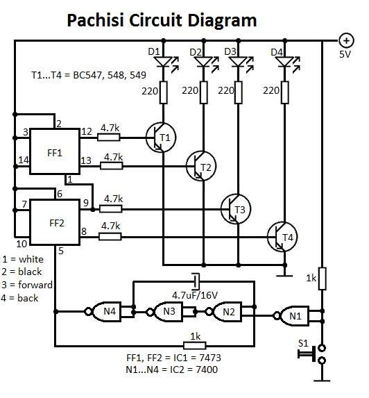
The Pachisi game is designed for two players. Each player has one figurine, which is initially placed on positions indicated by arrows on the game board. The Pachisi game, often referred to as the "Royal Game of India," is...