
100w inverter circuit 12vdc to 220vac

The circuit in question is designed to convert a 12 V DC input from a car battery into a specific output frequency of 50 Hz, which is commonly used in various applications such as powering AC loads or driving motors. The primary components of the circuit include the car battery, a potentiometer (R1), and a fuse.
The car battery serves as the main power supply, providing a stable 12 V DC voltage. To ensure safety and protect the circuit from overcurrent conditions, a 10 A fuse is placed in series with the battery. This fuse will blow if the current exceeds 10 A, preventing potential damage to the components and the battery itself.
The potentiometer R1 is a variable resistor that allows for fine-tuning of the output frequency. By adjusting the resistance of R1, the user can modify the timing characteristics of the circuit, which directly influences the output frequency. The circuit may include additional components such as a timer IC or an oscillator circuit, which would help generate the desired 50 Hz signal based on the adjustments made to the potentiometer.
Overall, this circuit is a practical solution for applications requiring a low-frequency AC output derived from a standard 12 V DC source. Proper attention to component ratings, especially the fuse and potentiometer, will ensure reliable operation and longevity of the circuit.You can use 12 V car battery as the 12V input power source. Adjust the potensiometer R1 to get the 50Hz output frequency. Use a 10 A fuse in series with the battery as shown in circuit. 🔗 External reference
Related Circuits
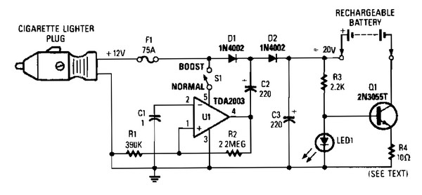
V1 creates a square wave oscillator, while D1 and D2 couple this square wave to a 12-V battery, raising the voltage to over 20 VDC. If this elevated voltage is not required, S1 can remain open. Q1 functions as...
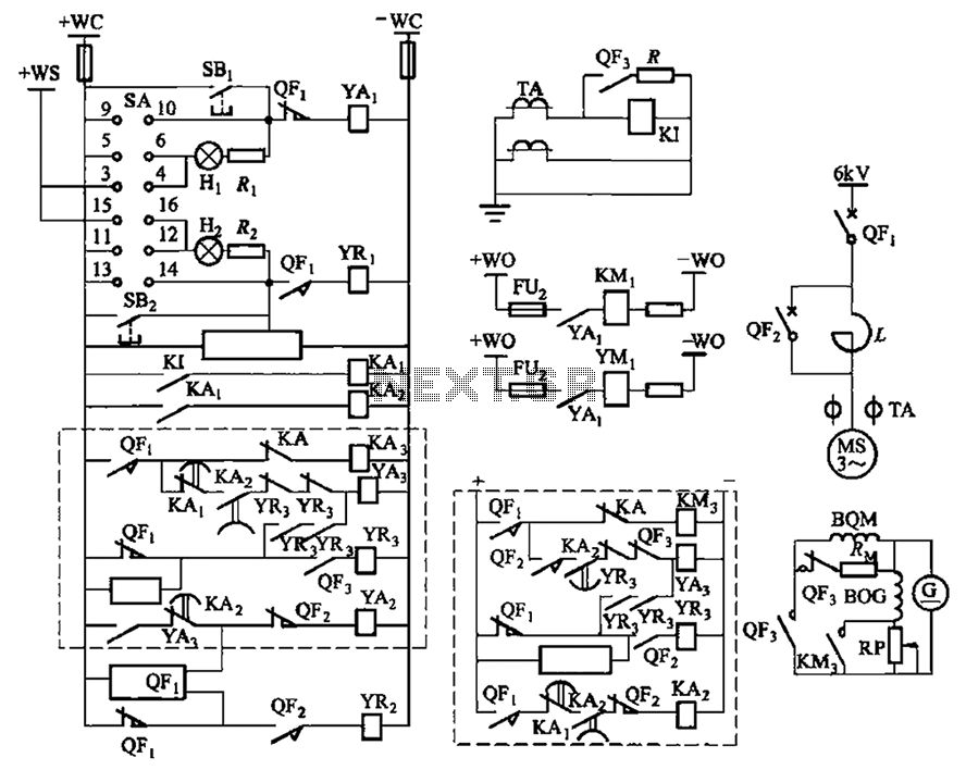
The circuit depicted in Figure 3-189 includes various components such as switch SA, closing button SBi, trip button SBz, de-excitation switch Yaa, and off trip coil YR3. The excitation switch contacts are represented by QF3, which serves as a...
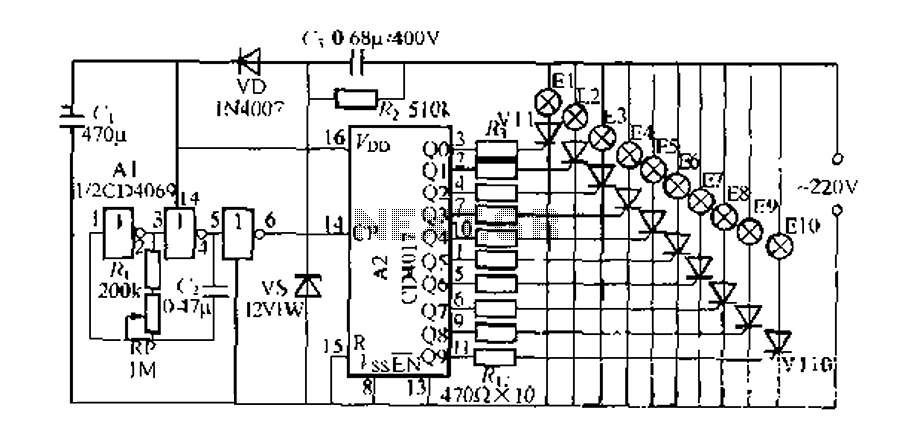
The digital integrated circuit consists of a controller for a string of ten road flashing lights, which drives the El-El0 string lights in a flashing cycle. The system utilizes a ten-count decoder, specifically the CD4017 digital integrated circuit. When...
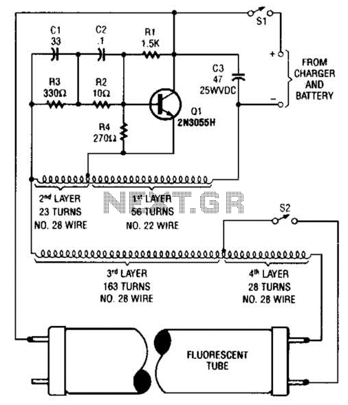
A 2N3055 oscillator (Q1) drives a homemade transformer, wound on a Vk ferrite rod. S2 is used as a filament switch and can be eliminated if desired. A 20-W fluorescent tube is recommended. The supply voltage is 12 V. The...
The following circuit illustrates a timer circuit with independent mark and space periods. It is based on the 7555 integrated circuit (IC). The high output duration is calculated by T(on) = 0.7 Ra Ct, while the low output duration...
This simple circuit is a good solution to the powering a dual supply op amp from a single battery problem. The circuit simply takes a positive voltage and inverts it. It uses only one 555 timer and a few...