
Build Own RFID circuit

Building a Radio Frequency Identification (RFID) system using a microcontroller involves several key components and a straightforward schematic design. The essential elements of an RFID system include an RFID reader, an RFID tag, and a microcontroller that processes the data from the reader.
The RFID reader is responsible for emitting radio waves that power the RFID tag and receive the information transmitted back. The microcontroller serves as the central processing unit, interfacing with the RFID reader to interpret the data received from the tags.
The typical schematic for a basic RFID system includes the following components:
1. **Microcontroller**: Select a suitable microcontroller, such as an Arduino or PIC, that has adequate I/O pins and supports the necessary communication protocols (e.g., SPI, I2C, UART).
2. **RFID Reader Module**: This module is connected to the microcontroller. Common examples include the RC522 or PN532 modules. The connections typically involve power (VCC and GND), and communication pins (MOSI, MISO, SCK, and SS for SPI communication).
3. **Power Supply**: Ensure that the power supply meets the voltage and current requirements of the microcontroller and the RFID reader. This may involve using a battery or an external power source.
4. **RFID Tags**: These tags can be passive or active. Passive tags are powered by the RFID reader's signal, while active tags have their own power source. The choice of tags will depend on the application requirements.
5. **Connecting Wires**: Use appropriate gauge wires to connect the microcontroller to the RFID reader and other components, ensuring reliable connections.
The schematic will typically illustrate the connections between the microcontroller and the RFID reader, including any necessary pull-up resistors and capacitors to stabilize the power supply and communication lines.
Programming the microcontroller involves writing code to initialize the RFID reader, continuously poll for tags, and process the data received. This can include reading unique identifiers (UIDs) from the tags and executing specific actions based on the tag data, such as logging information or triggering other devices.
In conclusion, building a simple RFID system with a microcontroller is achievable with basic electronic components and programming knowledge, making it a suitable project for educational purposes or hobbyist applications.how to build own RIFD, use one Microcontroller we can build it. This schematics is Very Simple 🔗 External reference
Related Circuits
Application circuit using three stereo digital potentiometers to control volume, balance, and fader in a four-speaker configuration with a push-button interface. The application circuit utilizes three stereo digital potentiometers, which are essential components for managing audio levels in a multi-speaker...
A DIY GSM jammer schematic diagram designed for use with GSM1900, operating within the frequency range of 1930 MHz to 1990 MHz. The GSM jammer circuit is intended to disrupt communication between mobile phones and base stations within the specified...
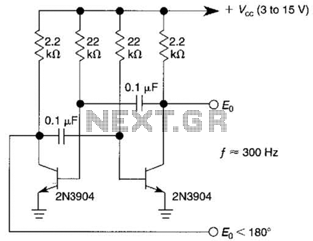
This free-running square-wave oscillator utilizes two NPN transistors. The output frequency is approximately 300 Hz with the specified component values. The circuit operates as a basic oscillator, generating a square wave output through the interaction of two NPN transistors. The...

This is a white LED lamp that activates when the telephone rings. The cool white light aids in locating the phone in low-light conditions and assists in managing clutter. The circuit for the white LED lamp that illuminates upon a...
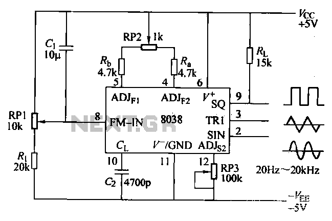
The ICL8038 function generator is an audio composition device that utilizes the ICL8038 integrated circuit. The resistance Ri potentiometer RP1 is used to determine the flow potential. Typically, the output is set to approximately 2Vcc / 3. Lowering the...
The ISO107 ripple reduction circuit includes an RC high-pass filter at the output to filter the output voltage ripple without impacting the DC characteristics. This configuration allows for a reduction of the 800kHz ripple voltage to less than 3mVp-p. The...