
build varying brightness ac lamp circuit

The varying brightness AC lamp circuit is designed to provide a flexible lighting solution by modulating the power supplied to a standard incandescent light bulb. The SCR plays a pivotal role in controlling the AC voltage applied to the lamp, effectively turning it on and off at a rapid pace, which results in perceived brightness changes. The integration of a 2K, 10-watt resistor is critical for voltage reduction, ensuring safe operation while also managing heat dissipation. Adequate ventilation is essential to maintain component integrity and prevent overheating.
The use of NPN transistors for half cycle detection allows for precise timing control, enabling the SCR to be triggered at calculated intervals. The 4017 decade counter serves as the core timing mechanism, with its outputs facilitating the adjustment of current levels, thus controlling the delay time before SCR activation. The design allows for a minimum delay of approximately 7 milliseconds, effectively rendering the lamp nearly off, while the full brightness state is achieved with minimal delay on the sixth output.
The circuit's ability to increment brightness in a linear fashion is enhanced by the configuration of resistors connected to the counter outputs, allowing for customizable brightness levels. This feature is particularly useful in applications where gradual light transitions are preferred, such as in mood lighting or theatrical settings.
The addition of a 47uF capacitor provides a smoothing effect on the brightness transitions, reducing the abrupt changes caused by the digital stepping of the counter. This enhancement results in a more aesthetically pleasing lighting effect, catering to user preferences for gradual dimming and brightening.
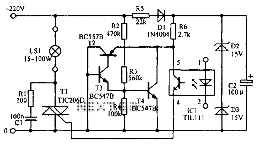
Overall, the varying brightness AC lamp circuit is a sophisticated solution for controlling light intensity, combining component selection and circuit design to achieve desired performance characteristics while ensuring safety and usability.Varying Brightness AC Lamp Circuit, an SCR is used to slowly vary the intensity of a 120 volt light bulb by controlling the time that the AC line voltage is applied to the lamp during each half cycle. The circuit is directly connected to the AC power line and should be placed inside an enclosure that will prevent direct contact with any of the components
. To avoid electrical shock, do not touch any part of the circuit while it is connected to the AC power line. A 2K, 10 watt power resistor is used to drop the line voltage down to 9 volts DC. This resistor will dissipate about 7 watts and needs some ventilation. A couple NPN transistors are used to detect the beginning of each half cycle and trigger a delay timer which in turn triggers the SCR at the end of the delay time.
The delay time is established by a current source which is controlled by a 4017 decade counter. The first count (pin 3) sets the current to a minimum which corresponds to about 7 milliseconds of delay, or most of the half cycle time so that the lamp is almost off. Full brightness is obtained on the sixth count (pin 1) which is not connected so that the current will be maximum and provide a minimum delay and trigger the SCR near the beginning of the cycle.
The remaining 8 counts increment the brightness 4 steps up and 4 steps down between maximum and minimum. Each step up or down provides about twice or half the power, so that the intensity appears to change linearly.
The brightness of each step can be adjusted with the 4 resistors (4. 3K, 4. 7K, 5. 6K, 7. 5K) connected to the counter outputs. The circuit has been built by Don Warkentien (WODEW) who suggsted adding a small 47uF capacitor from ground to the junction of the current source transistor (PNP) to reduce the digital stepping effect so the lamp will brighten and fade in a smoother fashion. The value of this capacitor will depend on the 4017 counting rate, a faster rate would require a smaller capacitor.
🔗 External reference
Related Circuits

An audio amplifier is an electronic device designed to amplify low-power audio signals, which primarily consist of frequencies ranging from 20 Hz to 20,000 Hz, the human range of hearing. This amplification is necessary to drive loudspeakers and represents...
The circuit diagram illustrates the LED signal amplification. The LED signal amplification circuit is designed to enhance the output signal from an LED, allowing it to drive larger loads or to be interfaced with other electronic components effectively. The primary...
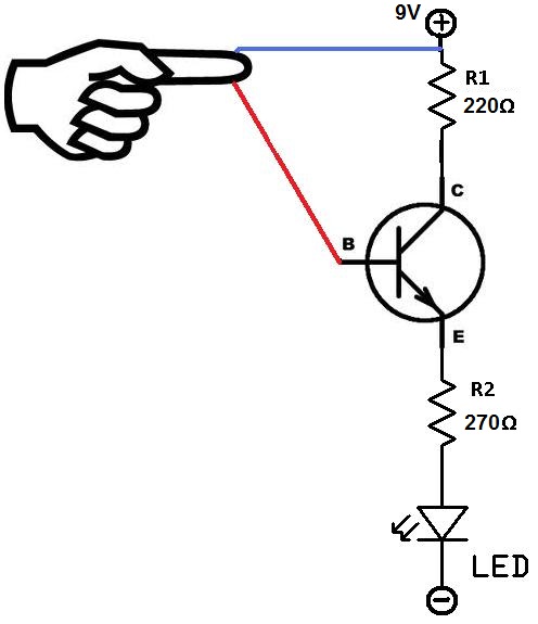
This project utilizes two wires, one red and one blue, which function as touch sensor wires. When a person touches both wires, the circuit closes, allowing current to flow and illuminate the LED. A 9-volt battery or an external...

The diagram illustrates the principle circuit of a radio control car receiver. Important notes include the selection of transistor Q1, which is specified as either 1815 or 9018, along with the bias resistor R1, which has values of 240K...
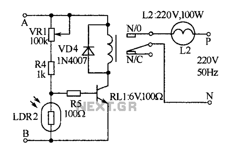
The receiver, as depicted in the figure, assists patients in avoiding missed audio signals during the daytime. The receiver operates independently, and the lighting will automatically turn off. At night, the lighting signal receiver activates simultaneously with the patient's...
The transmitter described here includes an additional RF power amplifier stage following the oscillator stage, which increases the output power to 200-250 milliwatts. When connected to a properly matched 50-ohm ground plane antenna or a multi-element Yagi antenna, this...