
LED signal amplifying circuit diagram

The LED signal amplification circuit is designed to enhance the output signal from an LED, allowing it to drive larger loads or to be interfaced with other electronic components effectively. The primary components of this circuit typically include an LED, a transistor, resistors, and capacitors.
In this configuration, the LED serves as the light source, which emits light when current flows through it. The transistor acts as a switch or amplifier, controlling the larger current that can be supplied to the load based on the input signal received from the LED. Resistors are used to limit the current flowing through the LED and to set the biasing conditions for the transistor, ensuring it operates within its safe limits. Capacitors may be included to filter noise and stabilize the circuit, ensuring smooth operation.
The circuit may be powered by a DC supply, and the output can be connected to various loads, such as additional LEDs, speakers, or other electronic devices. Proper design considerations, such as selecting the right transistor type (NPN or PNP), determining resistor values for biasing, and ensuring that the power supply voltage is compatible with the components, are crucial for achieving optimal performance and reliability of the LED signal amplification circuit. As shown in the circuit diagram for the LED signal amplification:
Related Circuits

The circuit illustrated in Figure 3-85 features both manual and automatic control through the transfer switch SA. After initiating the motor Mi, an automatic start sequence is achieved via the time relay KT. The circuit employs a transfer switch (SA)...

This is the circuit diagram of a line follower/line tracker robot. The circuit is derived from tutorial documentation, which can be downloaded at the end of this article. The line follower robot utilizes eight proximity sensor modules. Each sensor...
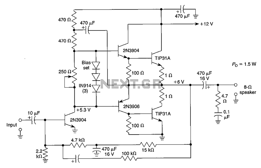
Although the integrated circuit (IC) has largely replaced this circuit, the flexibility of the discrete device design still makes it practical. The components are readily available and cannot easily be eliminated. If desired, a small piece of metal can...
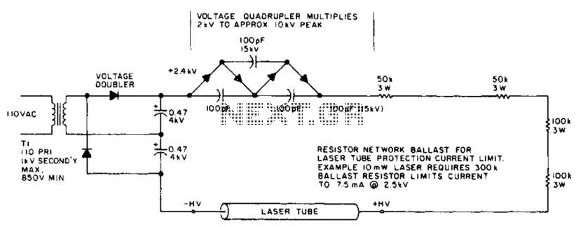
This circuit delivers a peak voltage of 10 kV, while limiting the current to 7.5 mA at 2 kV. The resistors included in the design serve the purpose of ballasting. Additionally, the starting circuit is unable to sustain the...
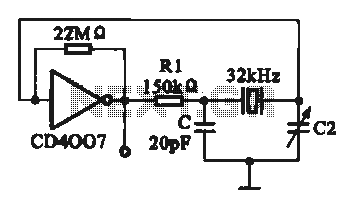
A 32 kHz clock oscillator is essential for digital circuits, as depicted in the schematic. The 32 kHz crystal clock oscillator serves to provide a time reference signal for the digital circuit. It utilizes a CMOS integrated circuit, specifically...
This document outlines a simple SWR (Standing Wave Ratio) protection circuit that can be easily constructed. The directional coupler and detector components are sourced from an old VHF SWR meter. It is advisable to replace the existing RF bypass...