
Radio control car receiver principle circuit diagram

The radio control car receiver circuit operates by receiving modulated signals transmitted from a remote control unit. The transistor Q1 serves as a key component in amplifying the received signals, with the choice of either the 1815 or 9018 model depending on the desired frequency response and gain characteristics. The bias resistor R1 is critical for setting the operating point of the transistor, ensuring optimal performance in the circuit.
The circuit includes capacitors C1 and C2, which are essential for filtering and tuning the receiver to the desired frequency. The specified values for these capacitors vary across different frequency bands, allowing the circuit to effectively handle the specific frequencies utilized in radio control applications. The inductors L2 are also tailored for the respective frequency ranges, with different inductance values being used to optimize the circuit's selectivity and bandwidth.
Inductor L1, produced using enameled wire with a diameter of 5mm, plays a vital role in the circuit's performance. The choice of wire gauge and winding technique affects the inductor's resistance and inductance, which are critical parameters for achieving the desired frequency response. Proper construction techniques must be employed to minimize losses and ensure reliable operation.
Overall, the design and component selection outlined in the circuit diagram are integral to the effective functioning of the radio control car receiver, enabling it to accurately receive and process control signals for the operation of the vehicle.Here is the diagram of radio controlcarreceiverprinciple circuit. Notes:The choice of transistor Q1 and the bias resistorQ1 1815 9018R1 240K 100K The choice of the high-frequency parameters partFrequency C1 C2 L227M 35P 30P 10uH35M 30P 30P 8.2uH40M 30P 20P 5.1uH49M 20P 15P 3.3uH The production method of L1In the diameter of 5mm, use Enameled wire diamet.. 🔗 External reference
Related Circuits
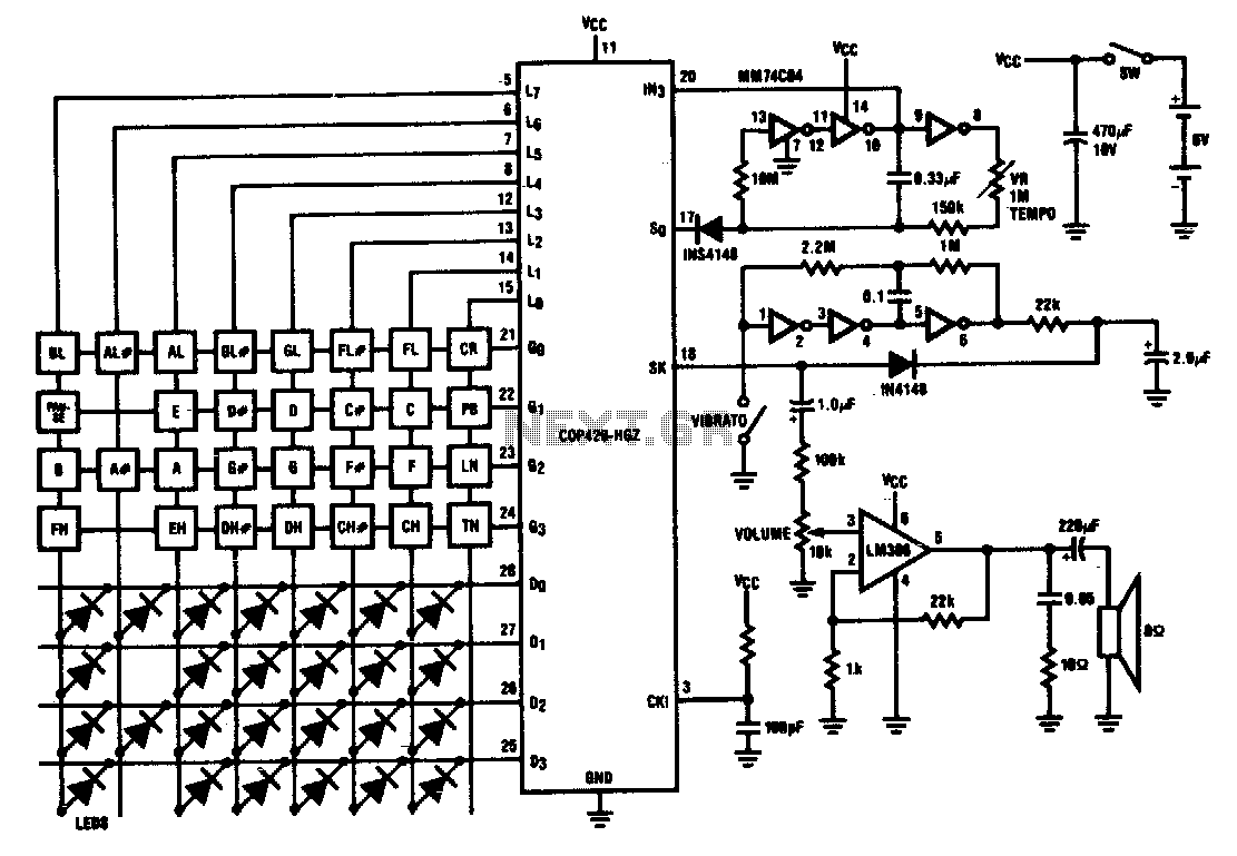
Twenty-five musical keys and 25 LEDs are provided to denote F to F" with half notes in between. Memory can store a played tune. There are ten preprogrammed tunes (each has an average of 55 notes) masked in the...
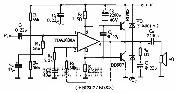
The rDA2030A TDA2030 is an enhanced version of the original product, with a maximum working voltage increased to 18V and a maximum output power of 18W. Additionally, harmonic distortion has been significantly reduced. The application circuit is illustrated. The rDA2030A...
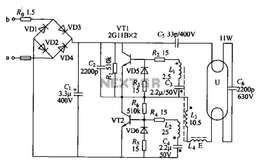
Energy-saving lamps are categorized into self-ballasted compact types and single-ended structures. They can also be classified based on appearance into various forms such as double-tube, four-tube, six-tube types, and others. The lifespan of energy-saving lamps is approximately ten times...
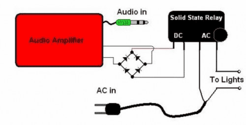
The basic Idea was to have Christmas lights flash with the music. In my design I use an ordinary amplified computer speaker, a diode bridge, and a ‘CRYDOM’ SSR (Solid State Relay). In order to increase the time that...

This is a design of the circuit diagram for an RS422 interface. Connector K1 is connected to the serial port of the PC, and power for the PC side of the circuit is obtained from the signal lines DTR...
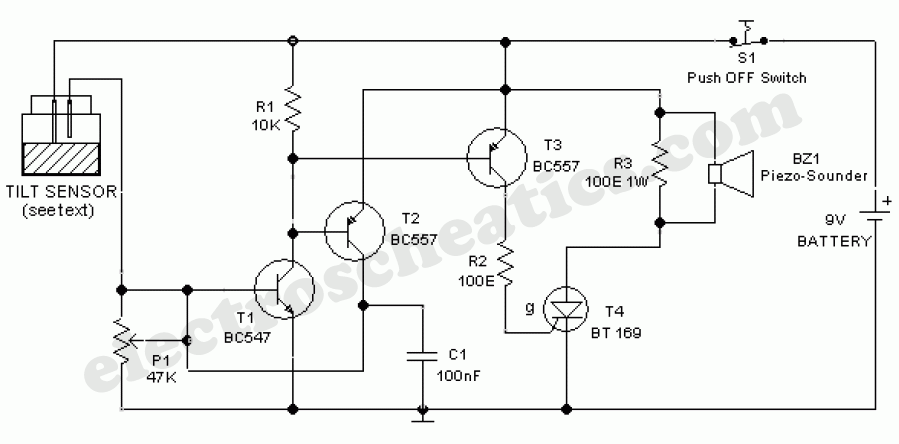
The ultra-simple tilt sensor alarm circuit can be constructed using readily available, inexpensive components. This circuit is based entirely on transistor technology. The homemade tilt sensor consists of a small glass or plastic bottle with two metal needles inserted...