
Build Your Own 555 Timer

The 555 timer is a popular device in electronics due to its ability to operate in various modes, including astable, monostable, and bistable configurations. In the astable mode, the timer generates a continuous square wave output, making it suitable for clock pulses and tone generation. In monostable mode, it produces a single output pulse in response to a trigger signal, which can be used for timing applications such as delays or pulse width modulation. The bistable configuration allows the device to act as a flip-flop, maintaining its output state until triggered by an external signal.
The internal architecture of the 555 timer consists of two voltage comparators, a flip-flop, a discharge transistor, and a resistor divider network. The comparators compare the input voltage to preset reference levels, determining the state of the flip-flop. The discharge transistor is used to reset the timing capacitor in monostable mode, while the resistor divider sets the threshold and trigger levels for the comparators.
The versatility of the 555 timer is further enhanced by its ability to interface with various components such as resistors, capacitors, and diodes, allowing for customizable timing intervals and output characteristics. Its wide supply voltage range, typically from 4.5V to 15V, and low cost make it an ideal choice for both hobbyist projects and professional applications. The 555 timer continues to be a fundamental building block in electronic circuit design, demonstrating its enduring relevance in the field of electronics.The 555 timer. A chip so versatile that it has been used in everything from toys to spacecraft. A chip that can act as an oscillator, a schmitt trigge.. 🔗 External reference
Related Circuits
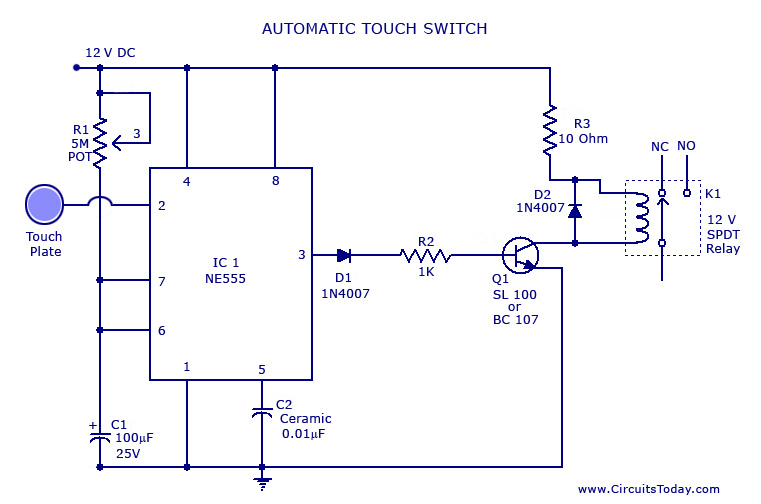
A touch switch circuit schematic utilizing a 555 integrated circuit (IC). When the touch plate is activated, a relay is switched ON for a predetermined duration, which can also be adjusted. The touch switch circuit employs a 555 timer IC...
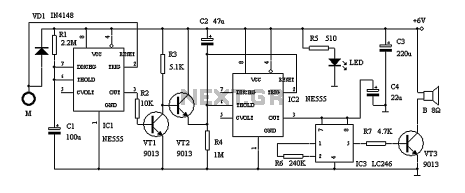
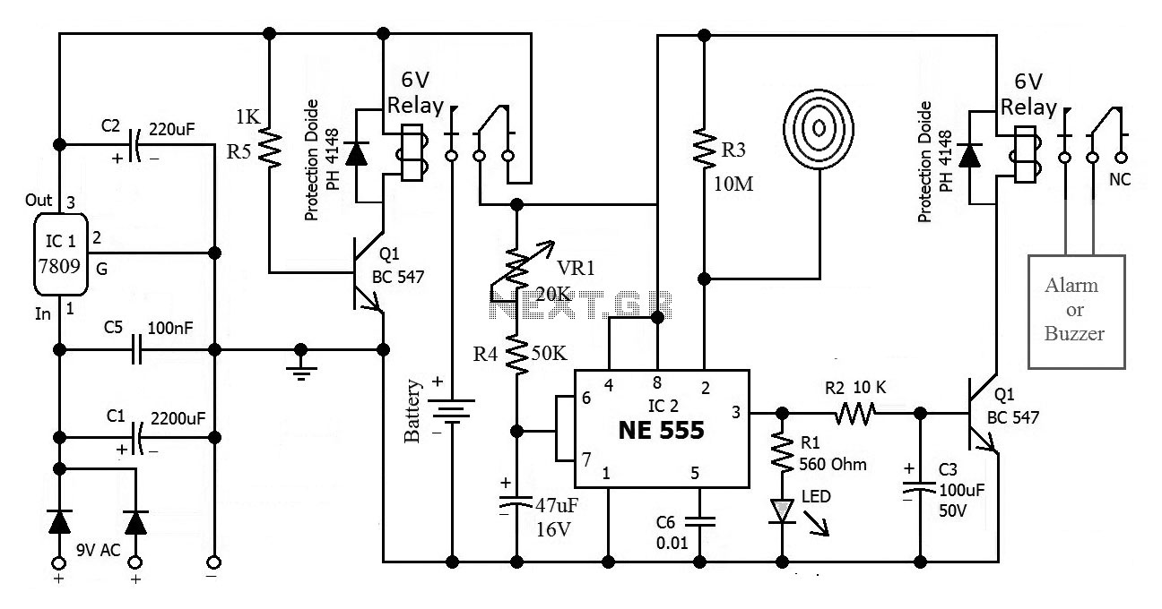
This circuit describes a door alarm system equipped with a time recognition feature. When the owner opens the door, it remains in a normal state for approximately 30 seconds without triggering the alarm. However, if the door is opened...
The overhaul includes features such as online judge diodes, the ability to test whether transistors are functioning properly, and the capability to assess TTL logic levels or high impedance states. It can output signals at 37 MHz, bar television...
This circuit utilizes two CMOS ICs: a 4011 quad 2-input NAND gate and a 4020 14-stage ripple binary counter. Upon powering on, resistors R2 and capacitor C2 generate a brief reset pulse, ensuring that the output pin Q1 of...
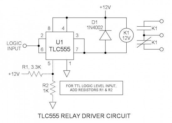
Many integrated circuits possess undocumented features or capabilities. One such example is the TLC555, which can sink a 100mA load down to 1.28V at its output (pin 3). The open-drain transistor reset (pin 7) can also sink 100mA to...
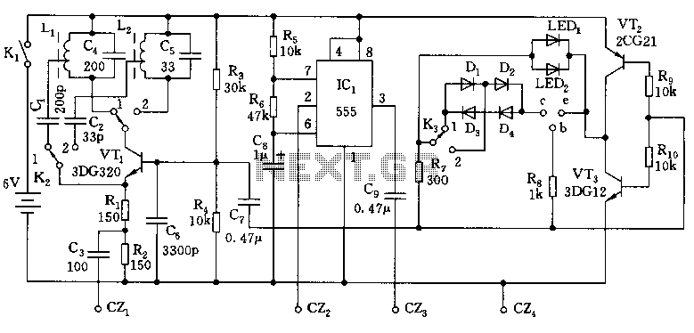
This is the circuit diagram of a touch-activated alarm system that remains operational during power outages. The alarm system is triggered when someone touches the designated touch plate. A notable feature of this circuit is the automatic battery activator,...