
555 multi-purpose repair circuit diagram

The described circuit is a multifunctional electronic testing and signal generation device designed for maintenance and troubleshooting of various electronic components, including transistors, diodes, and TTL logic circuits. The core of the system is built around a 555 timer configured as an astable multivibrator, which generates a square wave output. The frequency of this output can be adjusted by changing the values of resistors R5 and R6, as well as capacitor C8, allowing for versatility in testing different components.
The circuit employs multiple transistors, specifically VT1, VT2, and VT3, to control the flow of signals and to provide testing capabilities. The operation of these transistors is dependent on the output state of the astable multivibrator. When the output is high, VT2 is turned off, allowing current to flow through VT3, indicating a specific testing condition. Conversely, when the output is low, VT2 turns on, effectively disabling VT3. This switching mechanism is crucial for determining the operational status of the components under test.
LED indicators, LED1 and LED2, provide a visual representation of the test results, illuminating when a component is functioning correctly and remaining off when it is faulty. This feature enhances the user experience by allowing for quick and easy verification of component status.
The oscillator circuit formed by components VT1, L1, L2, and capacitors C1 through C7 is responsible for generating the AM signals required for radio and audio equipment testing. The output frequencies of 465 kHz, 930 kHz, and 1395 kHz are particularly useful for servicing older radio and tape recorder models, ensuring compatibility with various devices.
The switch K2 allows users to select between different operating modes. In position "1", the circuit outputs AM signals, while in position "2", it generates television signals at specified frequencies suitable for maintenance tasks. This flexibility makes the circuit an invaluable tool for technicians working with both audio and video equipment.
In summary, this circuit serves as a comprehensive testing and signal generation solution, incorporating a range of functionalities suitable for a variety of electronic maintenance applications. Its design emphasizes ease of use, reliability, and adaptability to different testing scenarios.The overhaul has the following features: online judge diodes, transistors is good or bad; test TTL logic level or a high impedance state; can output 37MHz, bar television signal 74MHz, 148MHz; the output 465kHz, 930kHz, 1395kHz AM signal. As illustrated, 555 and R5, R6, C8 composition astable multivibrator, the output added to the VT1, VT2 and so many were, as a test signal (200Hz). When the output is high, VT2 off, VT3 conduction; low, VT2 conduction. VT3 deadline. Test diodes, transistors, from LED1, LED2 luminescence, the tube can be judged good or bad. VT1, L1, L2, C1 ~ C7 and 555 point-frequency oscillators signal generating circuit. K2 "1" at, CZ1 output of the AM signal 465,930,1395kHz to repair radios, tape recorders, etc; K2 is set to "2", CZ1 TV output 37,74,148MHz bar signal for high frequency maintenance head and channel section.
CZ4 public places.
Related Circuits
The circuit consists of two 555 timer oscillators configured in a dual timer arrangement, both set up in astable mode. Components include a 1N4148 diode and a 555 integrated circuit. The dual 555 timer circuit operates in astable mode, generating...
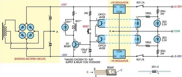
This circuit was designed to protect a dual rail power supply from shorts across the two rails. It uses an optocoupler to monitor each supply rail, with the internal LEDs powered from ZD2 and ZD3 and the associated resistors....
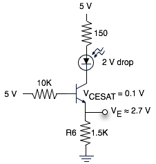
The schematic represents a relatively simple transistor circuit. Analyzing such schematics evokes memories of college days spent studying electrical engineering. However, the complexity of the schematic can be daunting after a long time away from the subject. To refresh...
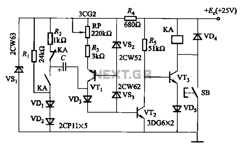
Charging time relay circuit 2 is a long delay circuit. When the capacitor C is 5000 µF, the delay can be up to 1.3 hours. Transistors VT1 and the VS2, VS3 group function as a constant current source to...
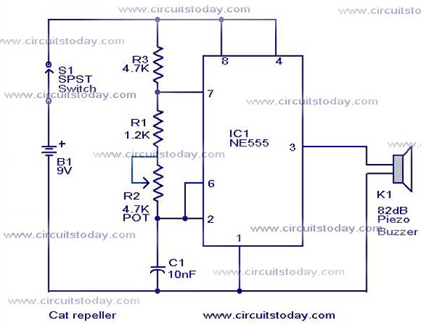
This cat and dog repeller circuit is designed to deter animals from specific areas. The circuit utilizes ultrasonic sound, which is known to provoke a strong response in many animals, particularly cats. The design features an astable multivibrator configuration...
A varying brightness AC lamp circuit utilizes a silicon-controlled rectifier (SCR) to gradually adjust the intensity of a 120-volt light bulb by controlling the duration of AC line voltage applied to the lamp during each half cycle. The circuit...