
Build your own LC-Display

The wiring of the display using a ribbon cable to a 25-pin sub-D connector involves several key steps to ensure proper functionality. The ribbon cable typically consists of multiple conductors arranged in parallel, which allows for efficient transmission of signals between the display and the controlling device.
To begin, the appropriate circuit diagram must be referenced, detailing the pin assignments for the sub-D connector. Each pin on the connector corresponds to a specific function or signal, and it is critical to adhere to this mapping to avoid connection errors. The soldering process should be performed on the rear side of the connector, which is where the pins are accessible for soldering.
Before soldering, it is advisable to strip the ends of the ribbon cable conductors to expose the wire. Each conductor should be carefully aligned with its corresponding pin on the sub-D connector as per the circuit diagram. The soldering should be performed with precision to ensure a solid connection, taking care not to create solder bridges between adjacent pins, which could lead to short circuits.
After soldering, it is important to inspect the connections visually for any possible defects. A multimeter can also be used to test for continuity between the pins and the corresponding conductors of the ribbon cable. Once the connections are verified, the assembly can be secured, and the display can be connected to the controlling device.
This process ensures that the display is properly wired and ready for operation, facilitating communication through the parallel port interface. Proper attention to detail during the soldering and connection verification stages is essential for successful implementation of the display wiring.For the wiring of the display we first of all take the ribbon cable and solder it according to the following circuit diagram on the 25 pin sub-d (parallel port) plug, whereby in my small circuit diagram I described the rear side - consequently the solder side of the plug: 🔗 External reference
Related Circuits
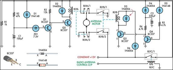
This up/down timer was designed to control a power antenna on a late-model vehicle. Normally, this vehicle uses a body computer to control the antenna. However, the owner intended to install a high-powered audio stereo system. The original stereo...
As with the Electronic sel. 8 we also have here a circuit with a choice of 8 different sources. The difference is that only two of the switches are used and the movement of commands is Up-Down in series....
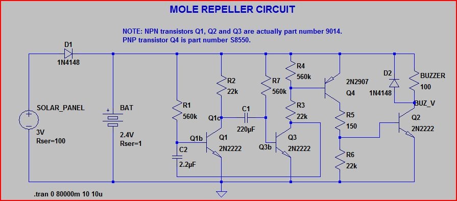
A healthy population of moles exists in the vicinity, prompting the purchase of four inexpensive ultrasonic mole deterrents from eBay to encourage them to relocate. The devices emit a frequency that is unpleasant to moles, leading them to vacate...
AM radio receivers demodulate amplitude-modulated (AM) signals. The primary source of these signals is the Standard AM Radio Broadcast Band, although shortwave stations also utilize AM modulation. Amplitude modulation was developed between 1900 and 1917 by amateur radio enthusiasts....
Wibowa Chou from IR discusses the benefits of fourth-generation IGBTs compared to MOSFETs, particularly in the context of a practical solar inverter application. Fourth-generation Insulated Gate Bipolar Transistors (IGBTs) offer significant advantages over Metal-Oxide-Semiconductor Field-Effect Transistors (MOSFETs) in various applications,...
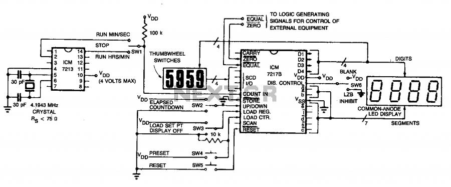
The circuit employs an ICM7213 precision timebase generator with a frequency of 4.1943 MHz, which is utilized for generating pulses that are counted by an ICM7217B counter. Thumbwheel switches are incorporated to allow the user to input a starting...