
Butler aperiodic oscillator

The circuit in question is designed to function optimally between 50 kHz and 500 kHz, making it suitable for applications that require precise frequency control within this bandwidth. The design allows for minor adjustments to components, enabling the circuit to adapt to higher frequency operations. When operating at frequencies above 3000 kHz, careful selection of the transistor is critical to maintain performance.
The transistor should be chosen based on its gain characteristics, specifically targeting a moderate gain between 60 and 150, which ensures that the circuit can maintain stability and efficiency at higher frequencies. Additionally, the gain-bandwidth product is a crucial parameter; a minimum of 100 MHz is recommended to ensure that the transistor can adequately amplify signals without distortion or loss of fidelity at elevated frequencies.
In practical terms, this means that the circuit may utilize a variety of transistors, including BJTs or FETs, depending on the specific application requirements. The choice of passive components, such as resistors and capacitors, may also need to be adjusted to accommodate the desired frequency response and to ensure that the overall circuit maintains its integrity across the intended frequency range. By adhering to these guidelines, the circuit can be effectively optimized for both moderate and high-frequency applications.This circuit works well in the range of 50 kHz to 500 kHz. Slight component modifications are needed for higher frequency operation For operation over 3000 kHz, select a transistor that provides moderate gain (in the 60 to 150 range) at the frequency of operation and a gain-bandwidth product of at least 100 MHz.
Related Circuits
The Hartley Oscillator is a valuable circuit for generating high-quality sine wave signals in the RF range (30 kHz to 30 MHz). However, at the upper limits of this range and beyond, the Colpitts oscillator is typically favored. Both...
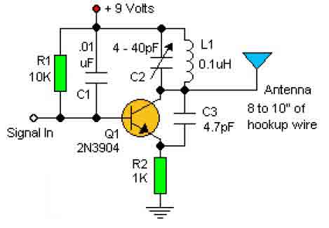
This basic RF oscillator circuit is easy to build and the components are not critical. Most of them can be found in your junk parts box. The L1 antenna coil can be made by close winding 8 to 10...
The Clapp oscillator is a type of electronic oscillator constructed from a transistor or vacuum tube and a positive feedback network. The Meissner oscillator circuit is a harmonic oscillator that consists of an active electronic element, such as a...

An early schematic of a Colpitts circuit utilizing a vacuum tube, redrawn from a patent publication. The Colpitts oscillator, invented in 1920 by American engineer Edwin H. Colpitts, is one of several designs for electronic oscillators. The Colpitts oscillator is...
This circuit is designed for low-power transmitters that operate with a positive keying voltage. The transistors Q1, Q2, and Q3 are configured as a switching amplifier. When the key is pressed, the collector of Q3 connects to ground, which...

A common issue in crystal sinusoidal oscillators is the excitation of unintended modes of the quartz crystal, which diminishes the spectral purity of the oscillator. This issue is particularly significant in overtone crystals, especially for low-voltage applications. In such...