
RF oscillator circuit (2N3904)
")
The RF oscillator circuit described is a fundamental design often used in various applications such as signal generation and testing. The circuit typically consists of a few essential components, including an oscillator stage, an output stage, and an antenna for signal transmission.
The oscillator stage is usually formed by a transistor, which can be configured in a common-emitter or common-collector arrangement, depending on the desired gain and frequency stability. The choice of transistor will influence the overall performance, but as noted, standard components can be utilized. The feedback loop is created using the inductor (L1) and a capacitor to set the oscillation frequency, which is determined by the formula f = 1 / (2π√(LC)), where L is the inductance and C is the capacitance.
In this design, the L1 antenna coil is a critical component, as it not only serves as an inductor for the oscillator but also acts as an antenna for radiating the RF signal. The construction of the coil is straightforward; by winding 8 to 10 turns of 22 gauge insulated wire around a suitable form, such as a pencil, the inductance can be adjusted by varying the number of turns or the diameter of the coil. This flexibility allows for experimentation with the oscillator's frequency, which can be observed by tuning a standard FM radio receiver to detect the emitted signal.
The coupling of the input signal to the oscillator stage is achieved using a disc capacitor of approximately 0.1µF. This capacitor serves to block any DC component while allowing the AC signal to pass through, ensuring that the oscillator can function effectively without interference from other circuit elements.
Overall, this RF oscillator circuit offers a simple yet effective platform for learning about oscillation, radio frequency transmission, and basic electronic principles. It provides an excellent opportunity for experimentation and understanding the relationship between component values and circuit behavior.This basic RF oscillator circuit is easy to build and the components are not critical. Most of them can be found in your junk parts box. The L1 antenna col can be made by close winding 8 to 10 turns of 22 gauge insulted hookup wire around 1/4 inch form such as a pencil. You can experiment with the size of the coul and the number of turns to see how it affects the frequency and signal output of the oscillator. You should be able to pick up its signal with standar FM radio receiver. The Signal In should be coupled by disc capacitor of about 0.1uF to the stage in front of it. 🔗 External reference
Related Circuits

When the preset is set to its maximum, the LED flashes at a rate of approximately once every half second. This rate can be increased by raising the capacitor value from 10µF to a higher value. For instance, if...
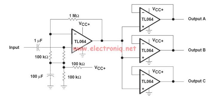
This audio distribution electronic project circuit diagram is designed using the TL064 or TL06 operational amplifiers and some other common electronic parts. The audio distribution circuit utilizes TL064 or TL06 operational amplifiers, which are quad op-amps known for their low...
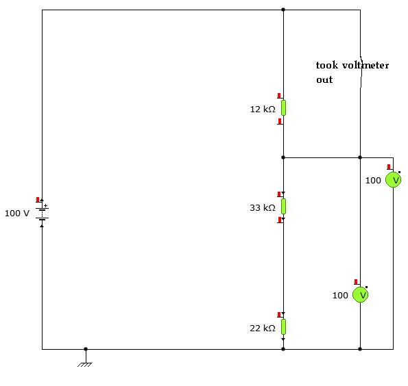
A user is utilizing YENKA software to diagram circuits but is experiencing confusion regarding the voltage calculations in a basic series circuit, as illustrated in the attached image. In a basic series circuit, components are connected end-to-end, forming a single...
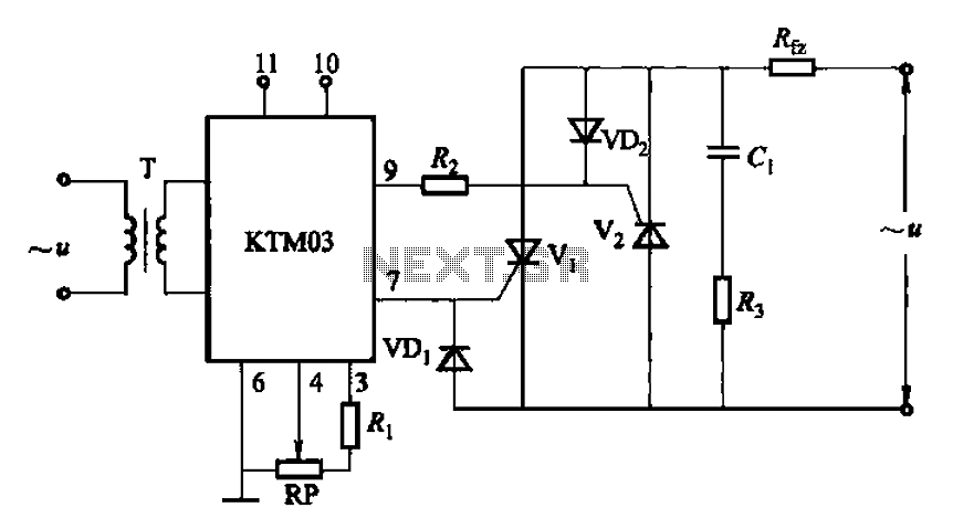
Adjustment potentiometer RP can modify the conduction angle of thyristor Vl, vz, thus altering the voltage applied across the load Rfz. The adjustment potentiometer (RP) serves a critical role in controlling the conduction angle of the thyristors Vl and vz within...
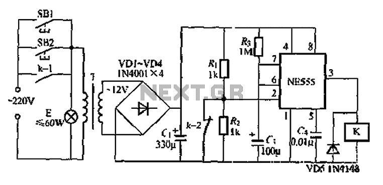
Another application involves the use of a NE555 delay lamp circuit, where components SB1 and SH2 act as J-light buttons that can be installed in two different locations. The lamp can be activated by pressing either SB1 or SB2,...
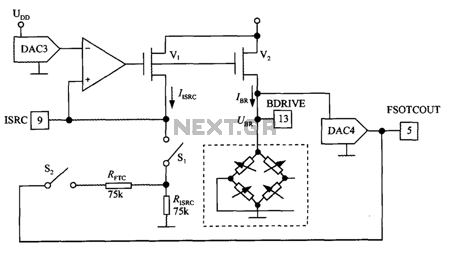
The excitation circuit for the digital pressure signal conditioner MAX1458 is illustrated. The output DAC3 is utilized to adjust the sensor excitation current (IBR), enabling full-scale fine calibration. The reference current (IISRC) is determined by the resistor RISRC and...