
Range precision voltmeter circuit

The schematic for the range precision voltmeter is designed to provide accurate voltage measurements across a specified range, utilizing key components that enhance its precision and reliability. The AD623 instrumentation amplifier is chosen for its low noise and high input impedance characteristics, which are critical for minimizing measurement errors. The precision voltage reference (IC1) ensures that the amplifier operates under stable conditions, allowing for consistent performance across varying environmental factors.
The resistor network consisting of R1, RPl, and R3 is configured to create a voltage divider that accurately scales the input voltage before amplification. This scaling is essential to ensure that the input voltage remains within the operational limits of the amplifier, preventing saturation and distortion of the output signal. The zero adjustment potentiometer (RPl) allows for fine-tuning of the baseline output, which is crucial for calibrating the voltmeter to provide accurate readings starting from 0V.
Gain adjustment is facilitated by potentiometer RP2, which alters the feedback loop of the amplifier. This feature is particularly useful for accommodating different ranges of input voltages, enabling the voltmeter to be versatile in its applications. The output from the amplifier is then processed through a voltage divider formed by resistor R4, which prepares the signal for display or further processing.
The header connected to the output provides a clear indication of the operational range of the voltmeter, with labeled start and end values that correspond to the selected input voltage range. This visual aid enhances usability, allowing operators to quickly ascertain the operational parameters of the device.
Overall, the design of the range precision voltmeter is focused on achieving high accuracy and reliability in voltage measurements, making it suitable for laboratory and industrial applications where precision is paramount. The integration of high-quality components and thoughtful design choices results in a robust instrument capable of delivering precise voltage readings over a defined range.Range precision voltmeter electrical schematic in Figure (a) below. Amplifier circuit and a number of high-precision components, which greatly improves the performance range of the voltmeter. IC2 inverting input instrumentation amplifier AD623 using a precision voltage reference source ICl do benchmarks. The positive input of Rl, RPl, R3 dividing the measured voltage is amplified. RPl to zero potentiometer, RP2 potentiometer to adjust the gain, the amplifier output voltage divider resistors R4 connected via a labeled start and end values of the header.
Select a range of measured voltage Vin, the starting value V1, the termination value V2, the measured voltage Vin varied within the range of V1 ~ V2. When you enter a standard voltage V1, adjust potentiometer RPl, the output of the amplifier meter is 0V, that is, the start value of the interval voltmeter; input voltage V2 standard, adjust potentiometer RP2, make the header that is full scale termination of the interval voltmeter.
Thus, the measured voltage change between V1 ~ V2 at the time, the first table pointer swing in the start and end values.
Related Circuits
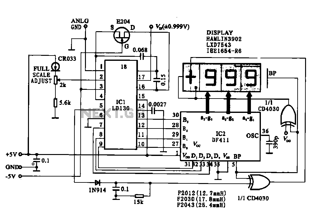
This circuit illustrates a display driving system for a digital voltmeter. The liquid crystal display (LCD) does not emit light by itself; it relies on external incident light for visibility. The integrated circuit (IC) LD130 serves as an input...
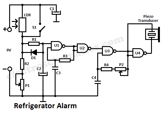
A simple light fence security beeper is presented. This circuit can function as a door alarm, gate alarm, pathway alarm, etc. It can be powered by any 12 Volt DC power supply. The operation of this circuit is straightforward....
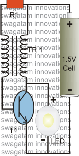
The post explains a simple 1 watt LED driver circuit using a single 1.5 V penlight cell through the joule thief concept. The coil may be wound over a T13 toroidal ferrite core using 0.2 mm or 0.3 mm...
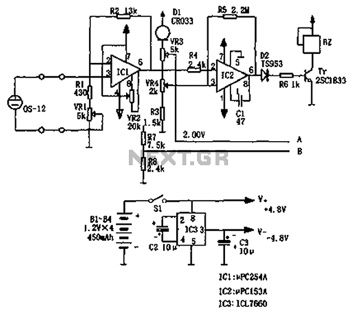
The circuit principle involves an oxygen sensor circuit utilizing the OS-12, a DC amplifier IC1, an A/D converter IC4, a liquid crystal display F2100-34PI, a voltage comparator IC2, and a positive and negative power converter IC, among other components....
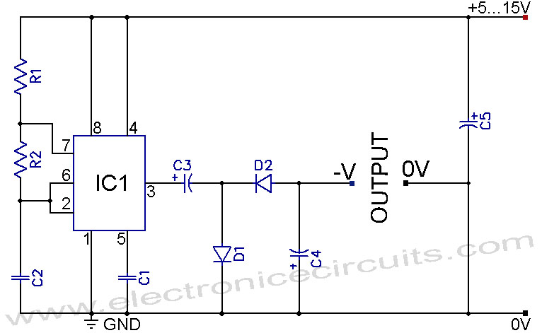
A 555 negative voltage power supply circuit can be created using a charge-pump configuration that incorporates a 555 timer, diodes, and additional components. The 555 timer is a versatile integrated circuit commonly used in various applications, including oscillators, timers, and...

This circuit diagram of a digital clock utilizes six common anode seven-segment displays to indicate the time. It does not require microcontrollers or PICs for operation. The circuit operates using the MM5314 integrated circuit, functioning at either 50 Hz...