
diy time lapse circuit

The DIY time-lapse circuit is a practical project that leverages the 555 timer IC's versatility in generating precise timing sequences. The circuit design typically includes a power supply, the 555 timer configured in astable mode, and the necessary interfacing components to connect to the camera. The power supply can be a simple battery pack, ensuring portability and ease of use.
In the astable configuration, the timing of the output pulses is determined by two resistors (R1 and R2) and a capacitor (C1) connected to the 555 timer. The frequency of the output pulse can be calculated using the formula:
\[ f = \frac{1.44}{(R1 + 2R2) \cdot C1} \]
Where \( f \) is the frequency of the output pulse. The total time for one cycle (the time interval between shots) is the sum of the time the output is high (T1) and the time it is low (T2), calculated as:
\[ T1 = 0.693 \cdot (R1 + R2) \cdot C1 \]
\[ T2 = 0.693 \cdot R2 \cdot C1 \]
Thus, the total time period \( T \) is:
\[ T = T1 + T2 = 0.693 \cdot (R1 + 2R2) \cdot C1 \]
By selecting appropriate values for the resistors and capacitor, the desired time-lapse interval can be achieved. Additionally, the inclusion of an LED indicator provides visual feedback, confirming the circuit's operational status, while the ON/OFF switch enhances convenience during setup and testing.
For further refinement, using a multi-turn trimmer potentiometer allows for precise adjustments to the timing, enabling users to fine-tune the interval for specific applications. This feature is particularly beneficial for projects requiring meticulous timing, such as nature photography or construction progress documentation.Here is information on how to build a diy time lapse circuit which will allows a camera to automaticly take photos between a certain time interval. Those photos then can be then to create time lapse film. It is used in this circuit a 2, 5 to 3, 5 stereo jack adapter which will be connected to the camera, a 3, 5 stereo jack cable and 3, 5 f
emale jack connector which will be connected to the circuit with wires. To test this out before assembling the circuit, connect everything and touch with a wire the ground of the female connector to one of the its tips and the camera should either focus or shoot (more info in ). It is possible to use only a 2, 5 cable by dismantling it and solder the wires directly to the circuit.
The main part of this circuit is the 555 timer IC which will control the time in the circuit. The 555 will be in astable (or oscillator) mode which will produce an output pulse on pin 3 during a certain amount of time, stop it during a certain amount of time and will keep repeating these two states. To prevent the camera to keep shooting during the period the circuit is outputting the pulse, it is necessary to disable the camera`s continuous shooting option so that camera only shoots one shot when the circuit starts to output the signal.
The time interval between shots will be one cycle of these two states, in another words, it will be the the amount of time that circuit outputs the pulse plus amount of that time that the circuit pauses before it starts outputting the pulse again. All you need now is to connected the battery as seen above and the circuit should be working. It is wise to add and ON/OFF switch to the battery and LED to check if the circuit is on or off. This calculator will calculate the value of the R2 resistor necessary to produce the desired time interval (which will be a 555 full cycle).
You can find another calculator along with more info here. a small suggestion: for more high precision timing you could use a multi-turn trimmer potentiometer, or maybe a high and low value variable resistor in series for course/fine adjustment. 🔗 External reference
Related Circuits
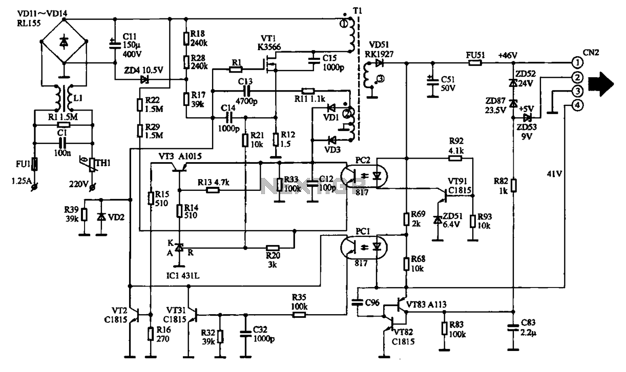
The EPSON PHOTO 830U printer power circuit illustrates the power supply circuit for the EPSON PHOTO 830U printer, which operates as a switching power supply. During normal operation, the power supply input socket receives a 220V AC supply to...
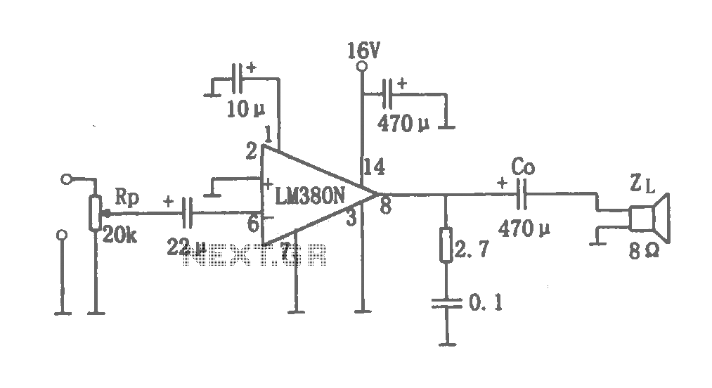
This document details a 2W audio power amplifier circuit that utilizes a 14-pin LM380 package as the amplification element. The input signal is managed by a volume control potentiometer (Rp) rated at 20k ohms, with a coupling capacitance of...
The high durability of a light-emitting diode (LED) makes it suitable for ON/OFF indicator applications. However, there are limitations regarding low operating voltage. Light-emitting diodes (LEDs) are semiconductor devices that emit light when an electric current passes through them. Their...
The following circuit illustrates a Boost Converter Circuit Diagram. This circuit is based on the 555 IC. Features: it only requires off-the-shelf components. The Boost Converter is a type of DC-DC converter that steps up the input voltage to a...
The circuits examined thus far rely on linear feedback for their operation. The magnitude of the signal returned to the negative input is always strictly proportional to the output voltage. Consequently, within the limits defined by the operational amplifier...

Figure 1-122 is a dedicated high-fidelity surround sound processing integrated circuit (IC) TDA3810 circuit that manages surround sound. The stereo signal is processed through input coupling capacitors C1 and C2. The internal buffer amplifier handles the left and right...