
cable tester uses quad latch

This cable testing circuit utilizes a systematic approach to identify faults within multi-core cables, particularly useful for audio applications. The core components include a microcontroller or latch IC (IC1), which is essential for maintaining the state of the outputs (LEDs) based on the input signals from the cable connections. The momentary contact push-button switch (S2) serves as a reset mechanism, enabling the user to initiate a fresh test cycle easily.
The circuit configuration allows for a straightforward connection of the cable under test between two designated sockets. Upon activation of switch S2, the latches are reset, and all four LEDs illuminate, indicating that the system is ready for testing. Each LED corresponds to a specific core of the cable, providing immediate visual feedback on the integrity of the connections.
In the event of a good connection, the relevant latches receive a high signal from the cable's core, which maintains the LED in an 'on' state. If a break occurs, the corresponding latches will receive a low signal due to the pull-down effect of the 10kΩ resistor, resulting in the LED turning off. This feature enables users to flex and twist the cable, allowing for dynamic testing that can reveal intermittent faults that may not be apparent under static conditions.
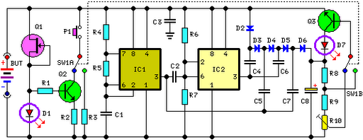
The circuit can be modified to test various cable types by replacing or adding appropriate sockets, thereby increasing its versatility. The design's simplicity and effectiveness make it an invaluable tool for audio technicians and engineers who require reliable cable testing solutions in their work.This circuit was designed to allow microphone cables or other cables to be easily tested for intermittent breaks that can often be difficult to find using a multimeter. The circuit can test cables with up to four cores. Both switches used in the circuit are momentary contact push-buttons and it can run from a 9V battery, in which case the 7805 reg
ulator can be omitted. To test a cable, connect it between the two sockets and press switch S2 which resets all four latches in IC1, setting them low. This turns on all four LEDs. A good connection for each core of the cable will mean that the relevant Set inputs of the latches (pins 3, 7, 11 & 15) will be pulled high and the appropriate LED will remain on.
A broken connection in the cable will result in the relevant Set input being pulled low by the associated 10k © resistor and the so the LED will be off. Because the circuit latches, it is easy to pinpoint even the smallest breaks by simply flexing and twisting the cable up and down its length until one of the LEDs turns off.
To test different types of cables, simply connect appropriate sockets in parallel with or in place of the XLR sockets. 🔗 External reference
Related Circuits
This circuit performs a rapid battery test without requiring a power supply or costly moving-coil voltmeters. It offers two testing ranges: when switch SW1 is positioned as indicated in the circuit diagram, the device can test batteries ranging from...
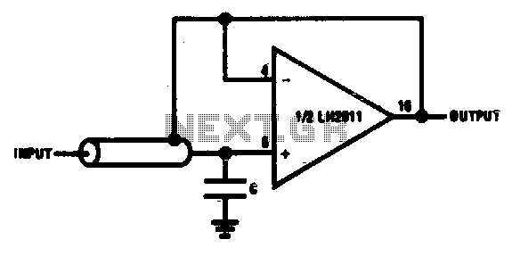
A bootstrapping input shield for a follower reduces cable capacitance, leakage, and spurious voltages resulting from cable flexing. Instability can be mitigated by using a small capacitor on the input. The bootstrapping input shield is a critical component in electronic...

This tester provides an audible indication of the logic level of the signal presented to its input. A logic high is indicated by a high tone, a logic low is indicated by a low tone, and oscillation is indicated...

If you have a servo and you want to test it but do not have a remote control or a dedicated tester, you can create a simple schematic for a servo tester. This circuit is based on a 555...
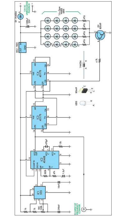
This stroboscope circuit utilizes 16 high-brightness white LEDs housed within a torch structure. It also offers a signal output to a frequency counter to indicate revolutions per minute (RPM). The stroboscope circuit is designed to provide visual indication of rotating...
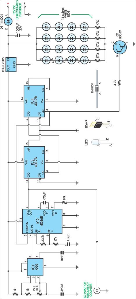
This stroboscope circuit employs 16 high-brightness white LEDs housed in a torch and provides a signal output to a frequency counter for rev counter display. The circuit utilizes IC1, a 555 astable multivibrator, which generates a signal for IC2,...