
Cable bootstrapping

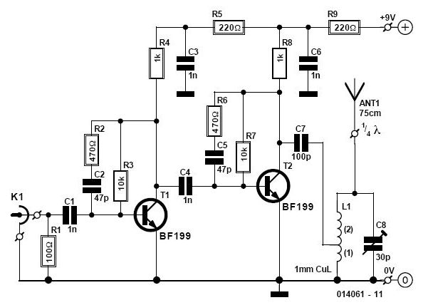
The bootstrapping input shield is a critical component in electronic circuits designed to improve signal integrity and reduce unwanted noise. This shield acts as a buffer, isolating the input signal from the effects of cable capacitance and leakage currents that can distort the signal during transmission. By minimizing these effects, the shield ensures that the follower circuit operates with greater accuracy and stability.
The design of the input shield typically incorporates a small capacitor placed strategically at the input stage. This capacitor serves to filter out high-frequency noise and stabilize the voltage levels, thereby preventing fluctuations that could lead to instability in the follower circuit. The value of the capacitor is chosen based on the specific application and the characteristics of the signal being processed.
In practical applications, the bootstrapping input shield is particularly beneficial in environments where cable movement is common, as it effectively reduces the spurious voltages generated by flexing cables. This is essential in maintaining the performance of sensitive electronic devices, such as audio equipment or precision measurement instruments, where signal fidelity is paramount.
Overall, the implementation of a bootstrapping input shield not only enhances the performance of follower circuits but also extends the longevity and reliability of electronic systems by mitigating the adverse effects of cable-related issues.Bootstrapping input shield for a follower reduces cable capacitance, leakage, and spurious voltages from cable flexing Instability can be avoided with small capacitor on input.
Related Circuits
In need for a cheap but effective RS-232 Protocol Analyser? Just make your own Y adaptor to enable the logging or display of data transmitted and/or received in ASCII, Hex, Decimal or Hex-Dump formats. A configuration file is included...
This circuit enables the use of a portable VHF FM radio to receive audio from stations that exclusively broadcast on the local cable network. This circuit operates by modulating the audio signals from the local cable network onto a carrier...
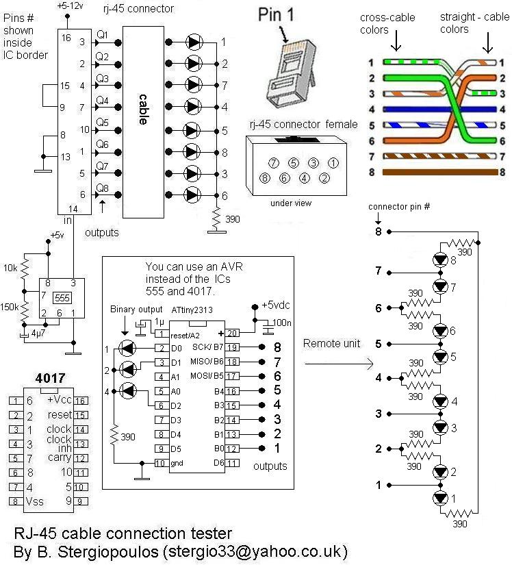
Here is a very simple yet practical circuit designed to check the type of LAN cables (straight or cross) as well as to identify possible faults. The circuit utilizes a unit with 8 outputs, each producing a pulse successively,...
A multi wire cable tester with a separate LED for each wire. Will show open circuits, short circuits, reversals, earth faults, continuity and all with four IC`s. Designed initially for my intercom, but can be used with alarm wiring,...
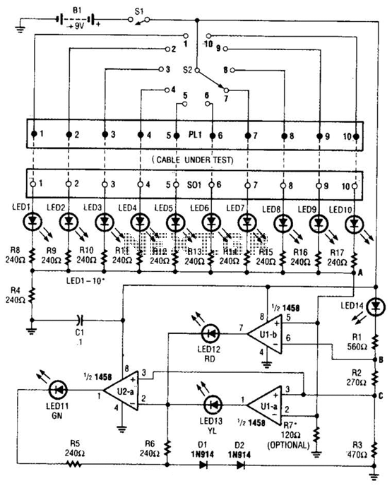
The cable tester utilizes two operational amplifiers (op-amps) configured as window comparators to detect short or open circuit conditions. A third op-amp comparator is employed to indicate a properly functioning circuit, meaning it is neither open nor shorted. Colored...
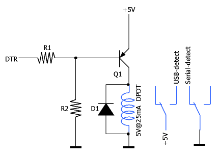
To ensure that the USB and serial segments are electrically isolated, an optocoupler (U1) is employed. The LED section of U1 is directly driven by the Data Terminal Ready (DTR) signal, necessitating the selection of a highly sensitive optocoupler...