
Calculator-to-stopwatch converter

The circuit utilizes a 555 timer configured in monostable mode to create a stopwatch function. When the push-on switch is activated, the timer begins to run, generating a pulse at a predetermined frequency. This frequency can be adjusted by changing the resistor and capacitor values connected to the timer, allowing for precise timing intervals.
The output from the 555 timer can be used to drive a display, such as an LED or an LCD, to visually indicate the elapsed time. In addition, the circuit can incorporate a second push-off switch that, when activated, will stop the timer and reset the display to zero.
To ensure compatibility with various calculator batteries, the circuit should include a voltage regulator to maintain a stable voltage supply to the 555 timer and any additional components. Proper filtering capacitors should also be included to reduce noise and improve the reliability of the circuit.
Overall, this stopwatch circuit enhances the functionality of standard calculators, providing an additional tool for users while maintaining simplicity and ease of use.This circuit can be fitted to any calculator existing calculator battery via the push-on with an automatic constant to enable it to be push-off switch and the existing calculator on-used as a stop-watch The 555 timer is set to off switch, run at a suitable frequency and connected to the.
Related Circuits
This document serves as a resource for developers who are new to Texas Instruments (TI) ARM-based processors, as well as for seasoned developers seeking to deepen their understanding of the different ARM architectures. It starts with an overview of...
The current loop interface circuit diagram of the AD694 multi-functional sensor signal conditioner is utilized as a digital-to-analog converter (DAC). This current loop interface enables the conversion of digital values into voltage and subsequently into current signals. The circuit...
This circuit utilizes a standard loudspeaker, enabling it to function as a microphone. It allows for the use of an inexpensive loudspeaker in this capacity. Sound waves impacting the speaker cone result in variations in the voice coil. The...
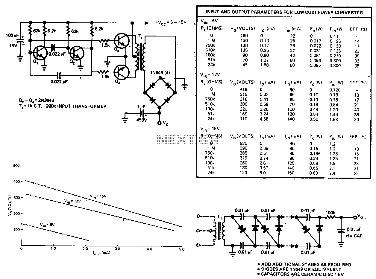
This circuit consists of an astable multivibrator driving a push-pull pair of transistors into the transformer primary. The multivibrator frequency should equal around 1 or 2 kHz. For higher DC voltages, voltage multipliers on the secondary circuit have been...
A high voltage step-up DC power supply using adjustable flyback conversion. The described circuit is a high voltage step-up DC power supply that employs an adjustable flyback converter topology. Flyback converters are widely used in applications requiring electrical isolation and...
Any step-down DC-DC converter can be utilized as an inverter without modifications to the operating schematic. The only differences between the standard step-down application and the inverting operation are the labels of the connection points. The step-down VOUT is... A...