
Camera Switcher

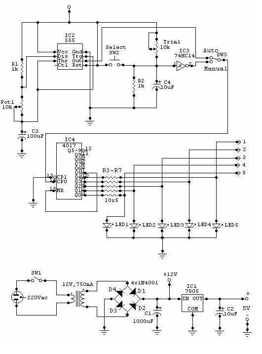
The circuit employs a 555 timer configured in astable mode to produce a square wave signal, which is fed into the clock input of a 4017 decade counter. The 4017 counter has ten outputs, but in this application, only the first five outputs are utilized to control the corresponding relays for the cameras. The output from the 555 timer determines the switching frequency of the cameras. The frequency can be adjusted using Pot1, allowing for flexibility in how quickly the camera feed switches.
Each output of the 4017 is connected to a transistor, which acts as a switch to control the relay for each camera. The relays are essential for connecting and disconnecting each camera from the monitor without any electrical interference. The activation of a transistor energizes its corresponding relay, allowing the selected camera to transmit its video feed to the monitor.
In manual mode, the user can control the switching of the cameras by pressing SW2. This switch generates a pulse that increments the counter, allowing the user to cycle through the cameras one at a time. The use of LED indicators provides visual feedback on which camera is currently active, enhancing the user experience. The entire system is designed to provide a seamless transition between multiple camera feeds, making it suitable for various applications such as security monitoring, live event broadcasting, or any scenario requiring multiple video inputs to a single output display.This circuit can be used for multiple cameras with one monitor. The circuit can be operated manually or automatically. When operated automatically the switch will be connected to the output of 555 astable multivibrator that will send a continous square wave in the 4017 counter. When counter is running, the 5 transistor will switch one by one. For example; when Q1 is turned on the relay connected to Q1 will energized which will connect Out1 (Camera1) with the input (Monitor). If Q2 is turned on, Out2 (Camera2) will connect to input. For manual operation; each time the SW2 is push, transition will occur(Logic 0 to logic 1). That transition will change the output of the counter. Every time the SW2 is push, the counter output will change. LED ½s are indicator to monitor which camera is connected to monitor. Pot1 is the adjustment for switching speed for the camera. Be the first of your friends to get free diy electronics projects, circuits diagrams, hacks, mods, gadgets & gizmo automatically each time we publish.
Your email address & privacy are safe with us ! 🔗 External reference
Related Circuits
In night photography, long exposures are common, sometimes lasting several seconds to several minutes. HDR techniques often require taking a series of nine or more photos. Holding a remote trigger for an extended period can be tedious, leading to...
This circuit can be utilized for multiple cameras with a single monitor. The operation can be manual or automatic. In automatic mode, the switch... This circuit is designed to enable the connection of multiple cameras to a single monitor, allowing...
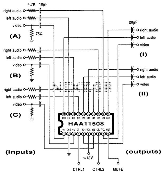
This channel selector selects video and stereo audio from any one of three different sources. The circuit should be constructed on a PC board with plenty of ground plane to minimize noise. The channel selector circuit is designed to facilitate...
This circuit incorporates a datasheet-compliant trigger signal, reversed polarity protection, an optional test button, and the capability for battery operation. It utilizes either the U1 L601E3 or MAC97A8 triac, rated for 400 V and 1 A. When U1 is...
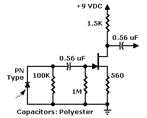
The JFET input configuration is utilized with PN photodiodes, such as the commonly used "bullet cell," which produce extremely low-level signals. Photodiodes provide several advantages over phototransistors, including a faster response to motion and a peak sensitivity within the...
The photometric camera for the SDSS consists of two TDI scanning CCD arrays: one featuring 30 Tektronix/SITe 2048 x 2048 CCDs arranged in a 5 by 6 array for five-color photometry, and the other composed of 24 2048 x...