
Can a Hartley Oscillator be built using Fixed Inductors

The Hartley oscillator is a type of LC oscillator that generates sine wave signals and is characterized by its use of inductors and capacitors to create an oscillation frequency determined by the values of these components. In a typical Hartley oscillator circuit, two inductors (L1 and L2) are connected in series, and a capacitor (C) is connected across the combination to form a resonant tank circuit. The feedback for the oscillator is provided through a tap on one of the inductors, which ensures that the circuit can sustain oscillations.
In this context, the use of two 22mH fixed inductors is appropriate, provided they are connected correctly to form the necessary feedback loop. It is essential to ensure that the inductors are not too tightly coupled, as excessive mutual inductance can lead to instability or prevent oscillation altogether. Therefore, the distance and orientation between the inductors should be optimized to achieve the desired coupling without impeding the oscillation process.
The transistor amplifier plays a critical role in the oscillator's operation, as it provides the necessary gain to sustain oscillations. If the transistor is functioning correctly when tested independently, the issue may lie in the feedback configuration or the values of the passive components. It is important to verify the connections and ensure that the feedback path from the inductors to the transistor is correctly implemented.
To achieve oscillation, the total phase shift around the loop must be 360 degrees, which can be affected by the values of the inductors and capacitor. Adjusting the capacitor’s value can help in tuning the frequency of oscillation. If no oscillation is observed when attempting to change the frequency, it may indicate that the circuit is not properly configured or that the components are not suitable for the desired frequency range.
In summary, the Hartley oscillator circuit requires careful consideration of component values, layout, and feedback configuration to ensure successful oscillation. If oscillation remains elusive, further investigation into component interactions and circuit design may be necessary to identify and resolve the underlying issues.An Hartley Oscillator circuit can be made from a pair of series connected coils. I had a couple of 22mH fixed inductors, which I hooked up on a breadboard with the other needed pieces. When I test the transistor amplifier independently, it seems to be working. However, there is no sign of oscillation in this circuit. So my ignorant question is, can I use the fixed inductors indicated I saw mention of the notion of `mutual inductance`, and I`m not sure you can get such with these discrete components. However, I clearly still have a long way to go, as when we attempted to change the frequency of the circuit we were mimicking, we got zero oscillation.
And the original Hartley circuit remains stubborn. 🔗 External reference
Related Circuits
An IR remote control is a widely used device found with televisions, VCRs, and home theaters. It can also be utilized to control personal devices such as lights and air conditioning. Remote controls operate using infrared (IR) light, which...
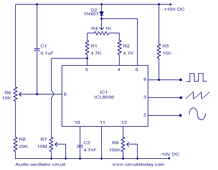
ICL8038-based audio oscillator circuit. Simultaneous sine, triangle, and square waveforms. Dual supply operation. Covers the full audio frequency range. The ICL8038 is a precision waveform generator integrated circuit that can produce sine, triangle, and square waveforms simultaneously. This versatility makes...
%2BCircuit%2Bdiagram%2Busing%2BCD4047%2Band%2BIRFZ44%2Bpower%2BMOSFET.png)
This simple low-power DC to AC inverter circuit converts 12V DC to either 230V or 110V AC. By making simple modifications, it is also possible to convert 6V DC to 230V AC or 110V AC. This inverter can be...
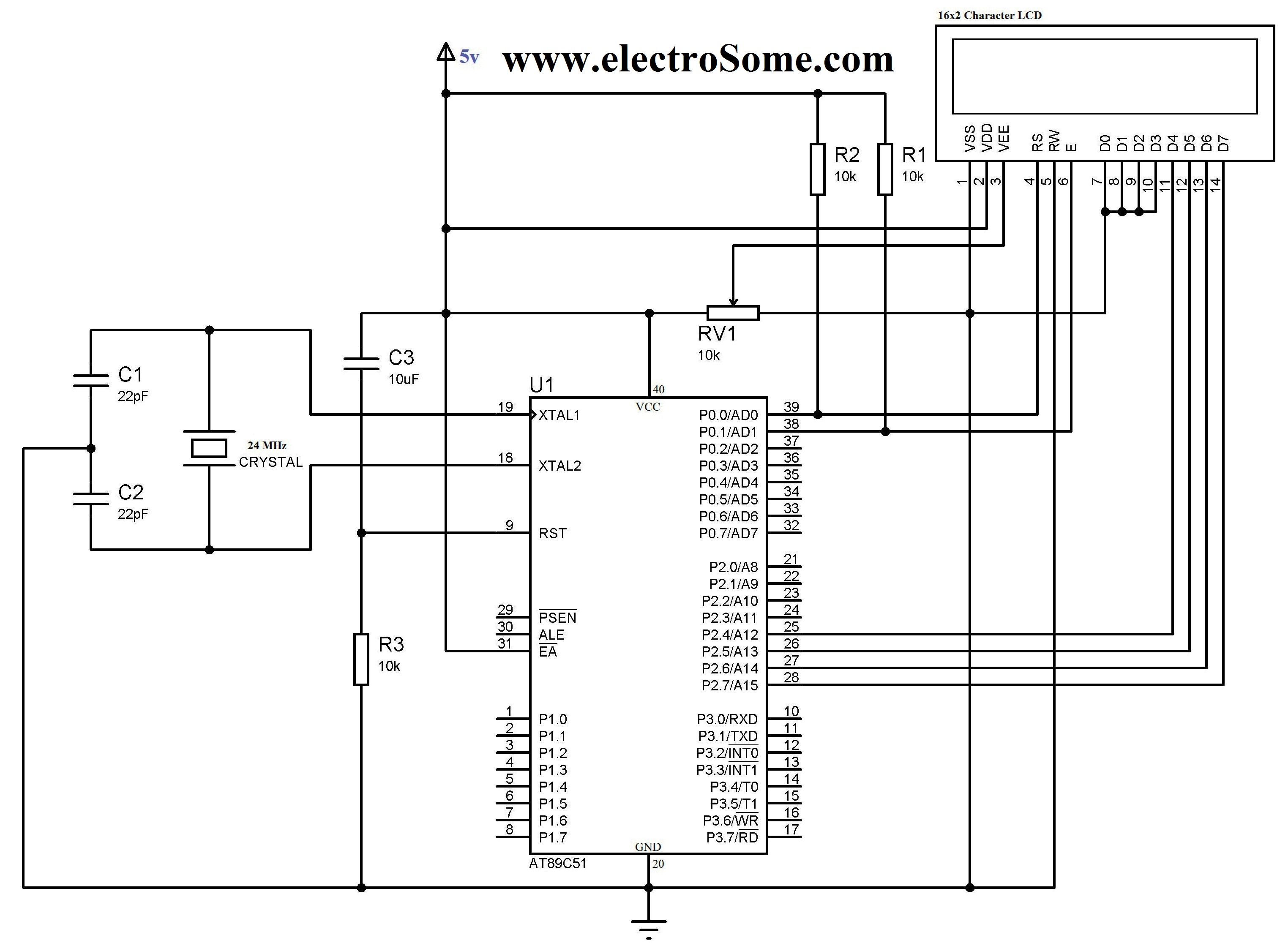
The 16x2 character LCD display is a basic module commonly utilized in electronic devices and projects. It can display 2 lines of 16 characters each. Each character is formed using a 5x7 or 5x10 pixel matrix. Interfacing the 16x2...
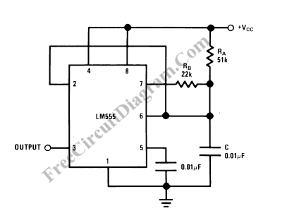
A square wave oscillator utilizing the 555 integrated circuit (IC) can be configured to produce symmetric oscillation with a 50% duty cycle. Additional circuit configurations employ diodes to separate the charging and discharging paths. The 555 timer IC is a...
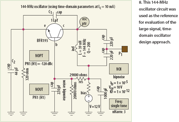
Unlike conventional small-signal methods, employing large-signal, time-domain design techniques facilitates the creation of low-noise grounded-base oscillators suitable for VHF/UHF applications. The development of low-noise grounded-base oscillators for VHF/UHF applications presents unique challenges and opportunities. By utilizing large-signal, time-domain design techniques,...