
Capacitance Meter Circuit

The simple capacitance meter circuit utilizes a frequency-to-voltage converter as its central element to measure capacitance values. This circuit typically operates by applying an AC signal across the capacitor under test, which causes the capacitor to charge and discharge. The frequency of the output signal generated by the circuit is inversely proportional to the capacitance value.
In this configuration, a known resistor is used in conjunction with the capacitor to form an RC timing circuit. The charging and discharging times of the capacitor are converted into a corresponding voltage level by the frequency-to-voltage converter. This voltage can then be displayed on a digital voltmeter or an analog meter, providing a direct reading of the capacitance value.
Key components of the circuit may include an operational amplifier configured as a comparator, a microcontroller for processing the output signal, and a display unit for reading the results. Power supply considerations are also crucial, as the circuit must maintain stable operation across varying conditions.
Calibration of the capacitance meter is essential to ensure accuracy, often requiring reference capacitors of known values to adjust the output readings. Overall, this simple capacitance meter circuit design enables effective measurement of capacitor values in various electronic applications.The circuit diagram of simple capacitance meter has been published here. The core part of this circuit is the frequency to voltage. 🔗 External reference
Related Circuits
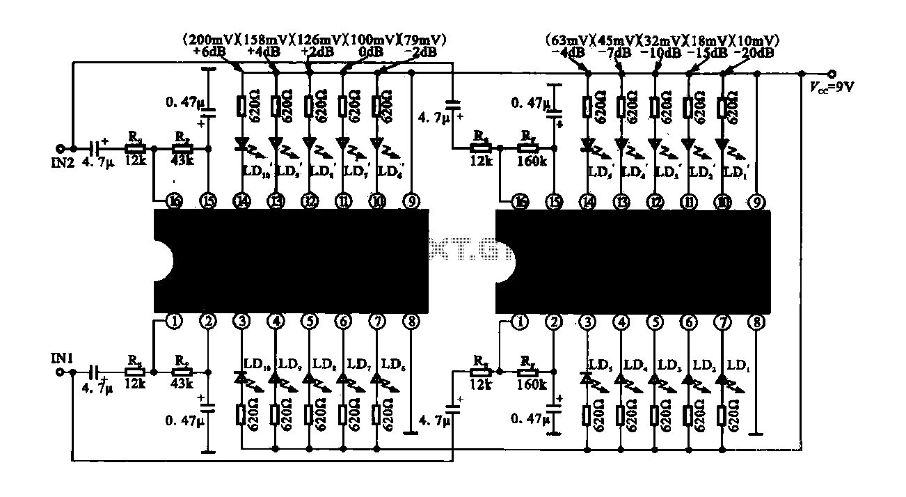
The circuit consists of dual drive integrated circuits (ICs) utilized in a 10 LED level meter configuration. The schematic features two TLM8101 driver ICs, which can be employed as alternatives. The 10 LED level meter circuit is designed to provide...
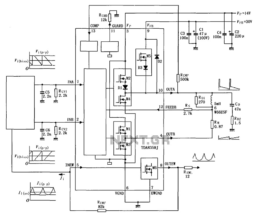
The TDA8358J application circuit is designed for television signal processing. The input signals are connected to the TDA8358J at pins 1 and 2, where pin 1 receives a positive sawtooth voltage input and pin 2 receives a negative sawtooth...
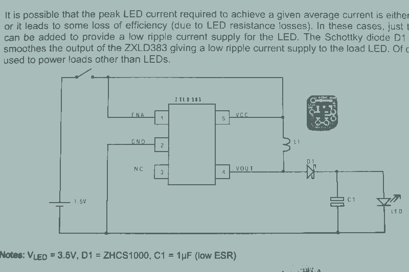
It may seem that due to the numerous flashlight projects undertaken, there is a significant collection of lights. The inductor can be altered to set the current level, but the total current fluctuates with the battery supply, decreasing as...

A simple circuit that can generate an inverted square wave similar to the one used by the inventor on his function generator. To construct a circuit that produces an inverted square wave, a basic approach involves using a 555 timer...
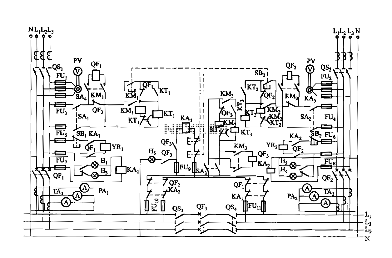
Dual power is provided for each complex, as the load is supplied through a two-way power system. In the event of a power outage, the contact switches transition from a closed position, allowing the power supply circuit to bear...
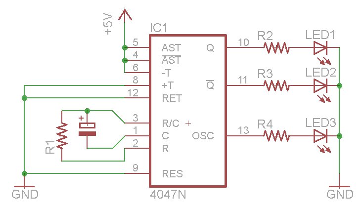
The oscillator output generates a signal that is approximately twice the frequency of Q. The other pins will be considered subsequently. In a brief video demonstration, LEDs are connected to all three outputs, illustrating the alternating behavior of Q...