
LOW frequency square wave oscillator circuit
Warning: Undefined array key "extension" in /var/www/html/nextgr/view-circuit.php on line 477
Deprecated: strtolower(): Passing null to parameter #1 ($string) of type string is deprecated in /var/www/html/nextgr/view-circuit.php on line 477

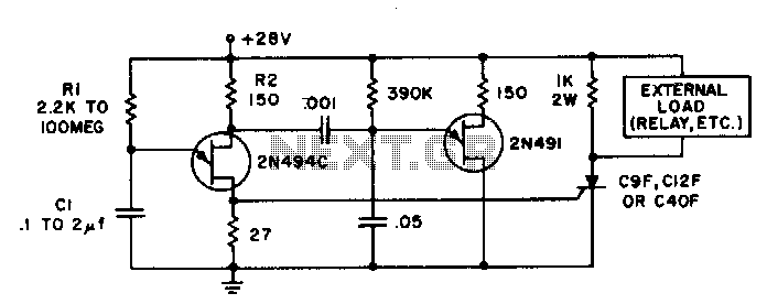
To construct a circuit that produces an inverted square wave, a basic approach involves using a 555 timer IC configured in astable mode. In this configuration, the 555 timer generates a continuous square wave output. For inversion, the output can be fed through a transistor or an inverter gate.
The circuit setup begins with the 555 timer connected in astable mode. Resistor R1 and resistor R2, along with capacitor C1, determine the frequency and duty cycle of the output waveform. The values of R1 and R2 can be calculated using the formula:
\[ f = \frac{1.44}{(R1 + 2R2) \cdot C1} \]
Where:
- \( f \) is the frequency of the output square wave.
- \( R1 \) and \( R2 \) are the resistances in ohms.
- \( C1 \) is the capacitance in farads.
For the inversion, the output from the 555 timer (pin 3) is connected to the base of an NPN transistor through a current-limiting resistor. The emitter is grounded, while the collector is connected to a positive voltage supply through a load resistor. When the output from the 555 timer goes high, the transistor turns on, pulling the output low, and when the timer output goes low, the transistor turns off, allowing the output to go high. This configuration effectively inverts the square wave produced by the timer.
Alternatively, a logic inverter (such as a 74HC14) can be used to achieve the same effect. The output from the 555 timer is connected to the input of the inverter, and the output of the inverter will provide the inverted square wave.
This simple circuit can be powered by a standard DC power supply, and with the appropriate component selection, it can be fine-tuned for specific frequency requirements.A real simple circuit that I can make that will give me the same inverted square wave the inventor is using The inventor calls out the setup he used on his funtion generator. 🔗 External reference
Related Circuits
This schematic illustrates a beeper circuit designed to produce a continuous beep sound while simultaneously flashing an LED. The beeper circuit typically consists of a few key components: a sound-generating device (such as a piezo buzzer), an LED for visual...
Time delays ranging from 0 milliseconds to over three minutes can be achieved with this circuit without the need for tantalum or electrolytic capacitors. The timing interval begins when power is applied to the circuit. At the conclusion of...
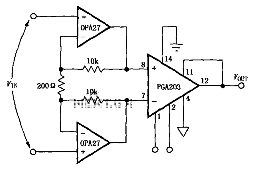
The circuit depicted in the figure features a PGA203 operational amplifier (op amp) and two OPA27 op amps, forming a low-noise differential amplifier. The input stage utilizes the PGA203 in conjunction with the two OPA27 op amps. The non-inverting...
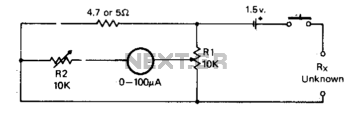
For the measurement of resistances ranging from approximately 5 ohms down to about 0.1 ohm. This circuit is highly practical. The described circuit is designed to measure low resistances with high precision, specifically in the range from 5 ohms down...
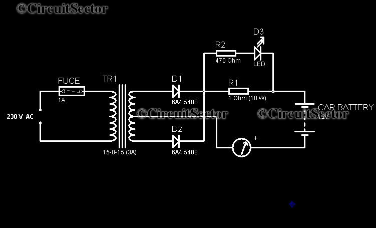
In today's world, owning a car battery charger at home has become essential. Having one readily available can help prevent starting issues caused by battery problems. While purchasing a commercial battery charger can be expensive, the components required for...
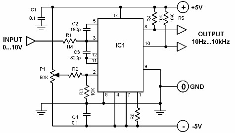
A voltage-to-frequency converter with a control range of 1:1000 can be constructed using the IC TSC9402. The specified component values in the circuit yield a conversion factor of 1 kHz per 1 V. Input voltages ranging from 10 mV...