
Capacitive Touch Sensor

In this design, an RC circuit is set up with a capacitor and a resistor in parallel. The microcontroller unit (MCU) charges the capacitor up to 5V. Once charged, the pin is switched to input mode, disconnecting the node and allowing the capacitor to discharge through the resistor. The discharge time is related to the resistor value multiplied by the capacitance. A resistor value of 100K ohms is used to ensure the RC time constant is measurable by the MCU. The sensor comprises two sheets of aluminum foil, one connected to the MCU pin and the other to ground, forming a capacitor that the MCU charges and discharges. When a hand moves between the sheets, it alters the electric field and, consequently, the capacitance. This change results in a longer discharge time, which is detected by the microcontroller's code.
An alternative implementation could use a pin change interrupt to measure the time taken for the pin to switch to a logic low level as the voltage drops. However, a more elegant solution is employed using the Analog Comparator on the chip. The Analog Comparator compares two analog voltages and outputs a binary signal depending on which is higher. A reference voltage, set to the bandgap voltage of approximately 1.2V, is used for comparison. This reference voltage allows ample room for the pin to discharge from 5V before changing the output state. The output of the comparator can trigger an interrupt when it switches from low to high, specifically when the capacitor voltage drops below 1.2V. This enables the timing of the voltage drop using a simple timer in the interrupt handler.
This design illustrates the integration of multiple concepts and components of the MCU to achieve a functional result. The slight change in capacitance, caused by the presence of a hand, can be measured by configuring the MCU as an oscillator and timing the discharge duration. Capacitive proximity sensors operate effectively because the human body, primarily composed of water, interacts with electric fields due to water's high permittivity, which is approximately 80 times greater than that of air. When a voltage is applied between the capacitor plates, an electric field is generated, and the presence of a dielectric, such as water, reduces the electric field strength compared to air.For this special Halloween project we built a spooky candy bowl that lights up when an unsuspecting trick-or-treater reaches in. While devices like these do exist, many of them use complicated proximity sensors to spring their trap.
Here at NerdKits we enjoy doingthings a bit differently, and making it easy for you to undertake it as a DIY project. Our proximity sensor is made using nothing but a NerdKit, two pieces of aluminum foil, and some paper clips! The actual sensor used to detect the presence of a hand in explained in detail in the video, but here is an overview. Our sensor operates on the same principle that a capacitive touch sensor works on your laptop touchpad.
These capacitive touch sensors work on the premise that humans are mostly water. When you get near an electric field you alter the capacitance enough to be noticed by the sensor. In our system we set up an RC circuit with a capacitor and a resistor in parallel. We use the MCU to charge capacitor up to 5V (a digital high voltage). Then we turn the pin into an input pin, which essentially disconnects that node. This allows the capacitor to discharge through the resistor. The amount of time it takes the capacitor to discharge will be related to the resistor value times the capacitance. We pick a resistor value large enough that the RC time constant is long enough for us to measure with the MCU.
In this case 100K ohms worked great. The sensor in this case is two sheets of aluminum foil, one connected to the MCU pin, and one connected to GND. These two sheets create a capacitor that our MCU is charging and discharging. When your hands move between the two sheets, it alters the electric field, and therefore the capacitance of our tin foil contraption.
The capacitor therefore takes longer to discharge, and that is detected by the code on our microcontroller! It might be possible to implement this with a pin change interrupt, and timing how long it takes for the pin to turn into a logic low level; that is, until the voltage drops low enough to be considered a 0 on the pin.
However, we chose a slightly more elegant approach. We use the Analog Comparator on the chip. The analog comparator does exactly what its name promises: it compares two analog voltages and outputs a 0 or a 1 depending on which one is higher. The Analog Comparator also allows you to designate a reference voltage to compare against. This voltage happens to be the bandgap voltage which is about 1. 2V. This 1. 2V is low enough that it gives the pin plenty of room to discharge from 5V before it changes the output of the comparison.
You can do anything you want with the output of the comparison, but the Analog Comparator allows you to set up an interrupt to fire when the output of the comparison switches from low to high (in our case this when the voltage on our capacitor drops below 1. 2V). With that we are able to time how long it takes for the voltage to drop, using a simple timer in the interrupt handler.
This is once again a great example of multiple concepts, along with multiple parts of the MCU working together to produce a very nifty result. Something as simple as a slight change in the capacitance can be measured by turning your MCU into an oscillator, and timing how long it takes to discharge.
Capacitive proximity sensors work because people are mostly water, and water is a very polar molecule, and is easily turned to align with any applied electric field. In fact, water has a "permittivity" (dielectric constant) that is about 80 times better than air! When a given voltage is applied between the two plates of any capacitor, an electric field is created between the plates.
In the region where there`s a dielectric, the electric field is actually smaller than it is in air (for water, just 1/80th of the field strength), so your first instinct might be 🔗 External reference
Related Circuits
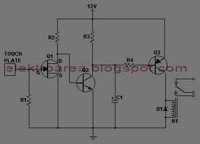
This document describes a series of touch switches that utilize only three transistors. These touch-based transistor switches can activate a load simply by the user touching a metal plate. They are designed to directly switch a relay, enabling operation...
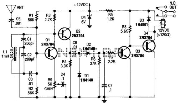
Q1 is used as an oscillator operating at approximately 300 kHz. Resistor R9 is configured to allow the oscillator to initiate its operation. An object near the antenna will load the circuit, causing the oscillations to cease. This change...
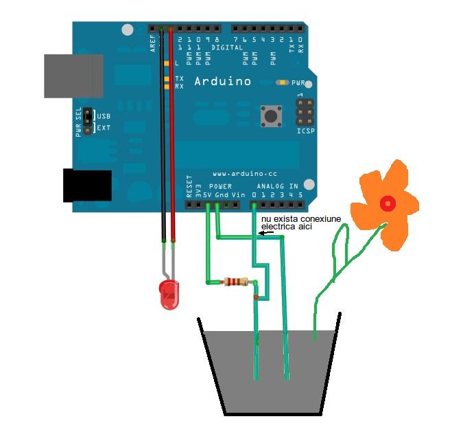
This is a simple Arduino project for a soil moisture sensor that will light up an LED at a certain moisture level. It uses the Arduino Duemilanove microcontroller. This project employs a soil moisture sensor to monitor the moisture content...
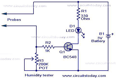
A simple humidity tester circuit using only an LED, a transistor, and a few resistors is explained with a clear circuit schematic. The humidity tester circuit is designed to provide a visual indication of humidity levels using basic electronic components....
This device is a highly effective capacitive sensor. In North America, it is primarily utilized for detecting wooden beams behind drywall or plaster. This model is preferred over newer designs due to its reliability, as it does not frequently...
Although the Arduino effectively captures incoming sensor data, executing code typically in the microsecond range, challenges arose in transmitting data between the Arduino and Max. The data transfer speed was insufficient. The focus was primarily on creative project realization...