
Stud Sensor Automatic circuit

The capacitive sensor operates by measuring the change in capacitance caused by the presence of a conductive or dielectric material. When the sensor is brought close to a wooden beam, the capacitance changes, allowing the device to detect the beam's location. This sensor typically consists of a sensing plate, a microcontroller for processing the signals, and an output interface, which may include visual indicators such as LEDs or audio alerts to inform the user of detection.
The design of this capacitive sensor is optimized for precision and reliability. It features a robust circuit configuration that minimizes false readings and enhances performance in various conditions. The sensor's sensitivity can often be adjusted to accommodate different materials and thicknesses of drywall or plaster, making it versatile for various applications in construction and renovation.
Power supply requirements for this capacitive sensor are generally low, allowing it to be powered by standard batteries or through a USB connection. The compact form factor ensures ease of handling and storage, making it an essential tool for professionals and DIY enthusiasts alike. Overall, this capacitive sensor stands out for its dependable operation and user-friendly design, making it a valuable asset in detecting hidden structures behind walls.This thing is a very nifty capacitive sensor. For you europeans, this little gem is used in north america mostly for detecting wooden beams behind drywall or plaster. I`ll take one of these over the new design any day, because these ones don`t error out every time you try to use them in a non-standard way.
🔗 External reference
Related Circuits
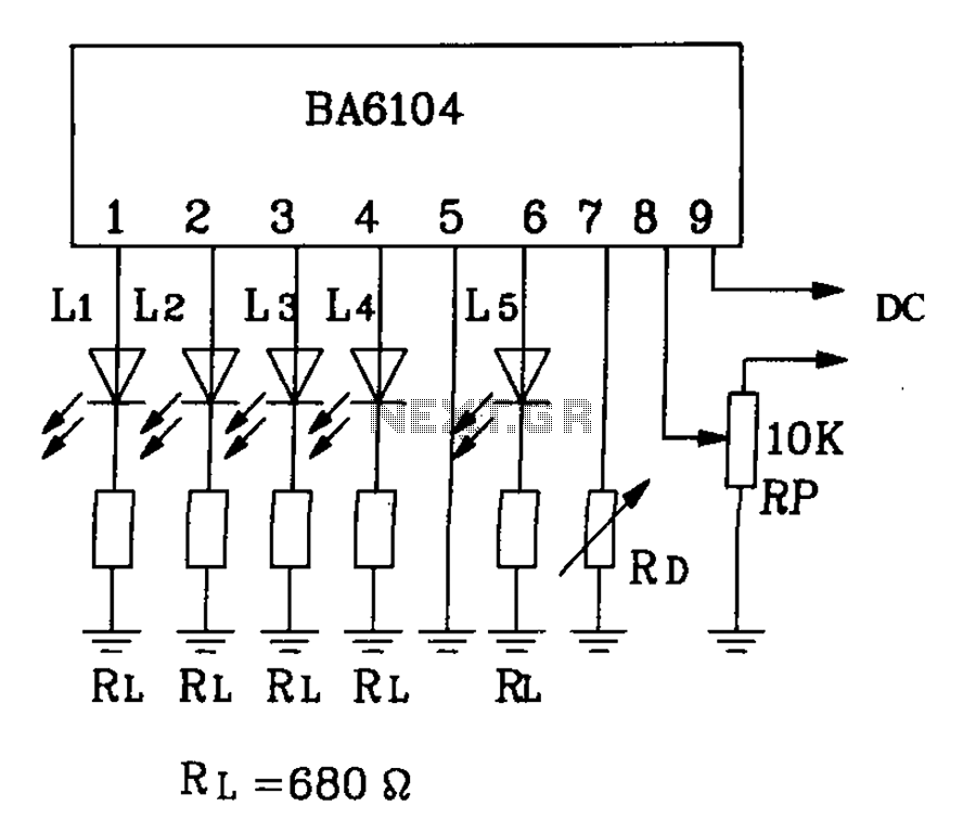
BA6104 is a five-digit LED level meter driver integrated circuit (IC) that features a basic application circuit. The input stage employs a PNP transistor with a composite base input, resulting in high input impedance. The output stage is configured...
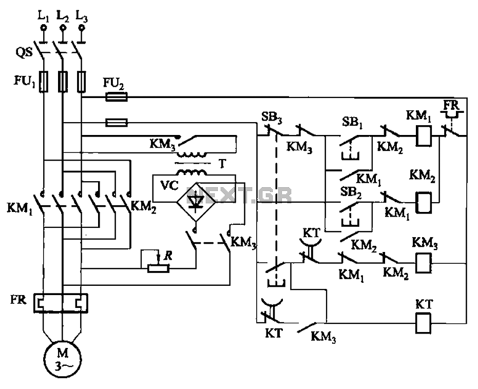
The circuit illustrated in Figure 3-144 depicts an automatic control system for dynamic braking. It utilizes a time relay (KT) to manage the operational duration, along with a step-down transformer (T) and a single-phase bridge rectifier. The circuit includes...
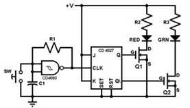
This project involves constructing a coin toss circuit that comprises three main sections: a square-wave oscillator, a JK flip-flop, and two LEDs (one red and one green). The circuit utilizes CMOS digital integrated circuits (ICs) and MOSFET transistors. The...
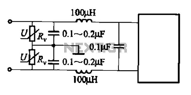
A common low-pass filter circuit is illustrated. Figures (a) to (c) demonstrate its ability to suppress high-frequency interference, while Figure (b) shows a varistor that can absorb lightning surge voltage. Figure (d) indicates the circuit's capability to suppress low...

The Quick and Easy Wireless circuit is not overly complex, but it requires careful verification of connections before initial operation. Key components in the circuit include the 7805 voltage regulator, the 18F452 microcontroller, an RC Receiver, and an RC...
The electronic pest-killing lamp circuit comprises an oscillator, control circuit, high voltage generator, LED indicator circuit, and power supply circuit. The schematic diagram illustrates these components. The oscillator circuit includes a time-base integrated circuit (IC), resistors R5 to R7,...