
Capacitor Allows Higher Slew Rates

This circuit utilizes a Burr-Brown operational amplifier known for its high performance and rapid response characteristics, specifically a slew rate of 135 V/μs. The slew rate is a critical parameter that defines how quickly an amplifier can respond to changes in input signal levels, making it essential in applications requiring fast signal processing.
The operational amplifier is configured with feedback components that include capacitor C2. The role of this capacitor is to modify the feedback loop's characteristics by reducing the high-frequency feedback factor to below unity. This adjustment is significant because it allows for the stabilization of the amplifier's response when operating at higher frequencies, where gain can exceed one.
By implementing this configuration, the circuit can effectively manage the gain of high slew-rate amplifiers, ensuring that they remain stable and do not oscillate or produce unwanted distortion at high frequencies. The design is particularly useful in applications such as audio processing, signal conditioning, and instrumentation, where maintaining signal integrity at high speeds is paramount.
Overall, this circuit exemplifies the careful balancing of feedback components and operational amplifier characteristics to achieve optimal performance in high-speed electronic systems. In this circuit, a Burr-Brown op amp supplies a slew rate of 135 V/. The addition of C2 charges the high -frequency feedback factor to less than unity, and allows higher slew-rate amplifiers to be compensated for greater-than-unity gain.
Related Circuits
A 2 µF capacitor is charged to approximately 340 volts, and the discharge is controlled by a silicon-controlled rectifier (SCR). A Schmitt trigger oscillator (74C14) and a MOSFET (IRF510) are utilized to drive the low-voltage side of a small...
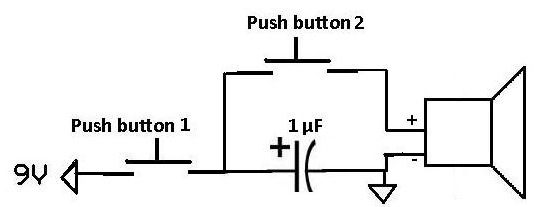
This project demonstrates how a capacitor can supply a pulse signal to a speaker. A capacitor is charged and then discharges its voltage to a speaker, which acts as a transducer that converts electrical signals into sound. The result...
Micropower and low-voltage operational amplifiers enable the construction of high-performance analog signal processors that do not require batteries or wall transformers. Instead, a capacitor can serve as the power source. The circuit illustrated in Figure 1 depicts an analog...
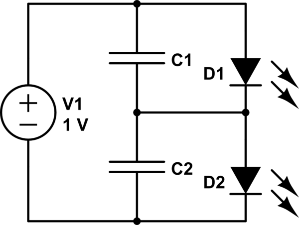
The first option is a Zener diode. There are several 2.2V Zener diodes available that could adequately protect the capacitor. However, a significant drawback is that half the energy may be wasted across the diode short. The question arises...
Switched-capacitor filters that are preset for a given bandwidth sometimes do not deliver the bandwidth or Q an application requires. By inverting the clock between two switched-capacitor bandpass filters, such as the MSFS1 from Mixed Signal Integration Corp, you...
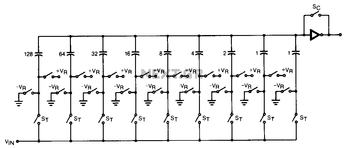
The CMOS comparator in the successive-approximation system determines each bit by examining the charge on a series of binary-weighted capacitors. In the first phase of the conversion process, the analog input is sampled by closing switch SC and all...