
Single Capacitor Powers Audio Mixer

The circuit employs a micropower design that enhances portability and efficiency, making it ideal for applications where battery replacement is impractical. The integration of a Supercap as a power source not only simplifies the design by eliminating the need for battery management circuits but also enhances reliability by removing the risks associated with battery leakage and chemical degradation. The LMC6574 op-amp's specifications ensure low power consumption while providing high fidelity audio processing capabilities. The design's flexibility allows for adjustments in gain and bandwidth, accommodating various audio signal processing needs. The straightforward architecture of the analog mixer, with its modular components, facilitates ease of troubleshooting and customization, making it an excellent choice for both hobbyists and professionals in the audio engineering field.Micropower and low-voltage op amps allow you to build high-performance analog-signal processors that require no batteries or wall transformers. Instead, you can use a capacitor as a power source. The circuit in Figure 1 shows an analog mixer designed for audio editing that you can connect between a camcorder and a VCR.
A capacitor, such as a Super cap or Dynacap, exclusively powers the circuit. These capacitors have values from 0. 047 to 1. 5F and maximum operating voltages of either 5. 5 or 11V. The capacitor in Figure 1 is approximately 1. 5 in. wide and 1 in. high, which is a reasonable size for a portable design. Using a capacitor as a voltage supply has many potential advantages vs regular disposable or rechargeable batteries. The Supercap has a typical charge time of 10 to 20 sec. To charge the capacitor, you can use any regular wall transformer unit with a filtered or unfiltered, regulated or unregulated, 5 to 10V-dc output.
There is no risk of overcharging the capacitor and therefore no need for accurate charge-current and time monitoring. Capacitor charge/discharge cycles are practically infinite. These voltage supplies have no disposable parts and no leaks. When using a capacitor, there is no chemical contamination or oxidation of electrodes. The capacitor can withstand short circuits for an unlimited time and may be discharged to any level without damage.
You can easily connect capacitors in parallel without side effects, such as bias current between paralleled batteries. The analog-signal processor in Figure 1 centers on the rail-to-rail, low-voltage, micropower quad LMC6574 op amp.
This op amp`s specifications make it suitable for this portable-audio application. The op amp can operate from supply voltages as low as 2. 7V with guaranteed rail-to-rail operation, typical supply current of 40 µA/amp, and THD less than 0. 1% in the audio-frequency range. The circuit is straightforward. Supercap C1 with C2, C3, R1, and R2 form the split supply with a virtual ground. Three stages of the LMC6574 with accompanying discrete components comprise the microphone amplifier. The three-op-amp topology provides good dynamic performance and low distortion. (Any stage has a maximum closed-loop gain of 10. ) The first stage, IC1A, performs bandpass filtering to remove high- and low-frequency noise. The frequency bandwidth for the microphone input is approximately 100 Hz to 10 kHz. To extend the upper cutoff frequency, you need to reduce C4 to 100 pF. You can adjust the gain of the second stage, IC1B. The third stage, IC1C, is an inverting amplifier with a gain of 10. IC1D works as an inverting signal mixer with unity gain. The circuit targets a standard load of 100 kilohms with a guaranteed 1V p-p output signal in a supply-voltage range from 2. 7 to 10V. Actually, the load capability of the LMC6574 is much higher, which makes the circuit and its variations fairly universastitute the LPC660 family of parts, but the circuit will start operating at 5V instead of at 2.
7V. If an application fits a more limited frequency range, biomedical instrumentation below 1 kHz for instance, you can use the LMC6044 and LMC6064 families, which have typical supply currents of 10 and 16 µA/amp, respectively. These currents dramatically lengthen the continuous supply time of the Supercap. 🔗 External reference
Related Circuits
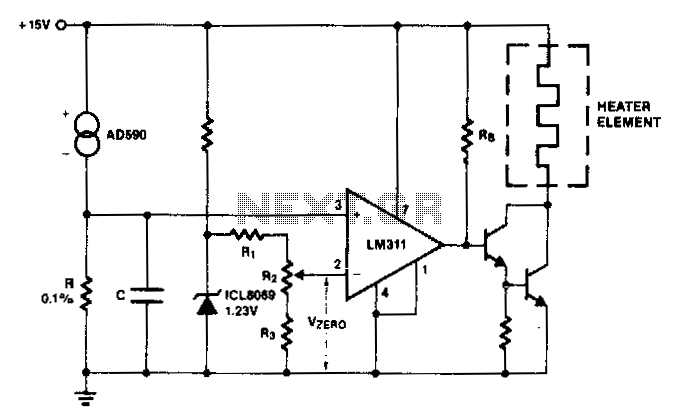
The AD590 generates a voltage that varies with temperature across resistor R, while capacitor C serves to filter out noise. To establish a zero-scale voltage, resistor R2 is adjusted. For the Celsius temperature scale, R should be set to...
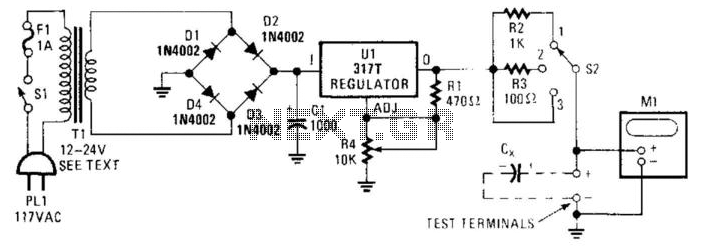
Sometimes electrolytic capacitors that are stored for a period may exhibit high leakage currents. Before utilizing these capacitors, it may be necessary to reform them. This power supply can be employed for the reforming process. Adjust resistor R4 according...
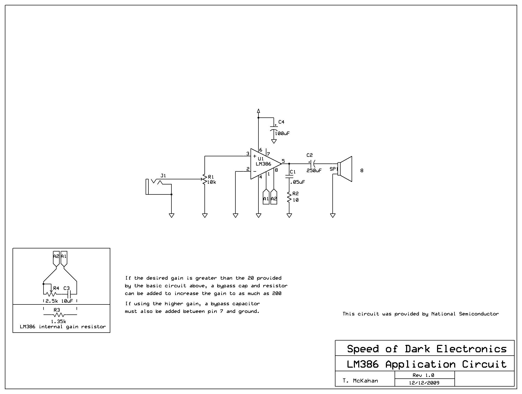
An LM386 Low Voltage Audio Amplifier was utilized for a project. The associated data sheet from National Semiconductor indicates that only five components are necessary for achieving a gain of 20, while seven components are required for a gain...
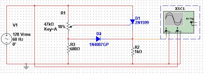
In previous discussions, simulations of half-wave and full-wave rectifiers using standard diodes were presented. This post transitions to the power electronics domain, focusing on a Single Phase Half-Wave Rectifier utilizing a thyristor, also known as a Silicon Controlled Rectifier...
A simple FM transmitter connects a home entertainment system to a portable radio that can be moved around the house and into the backyard. For instance, music can be played from a CD player in the living room and...
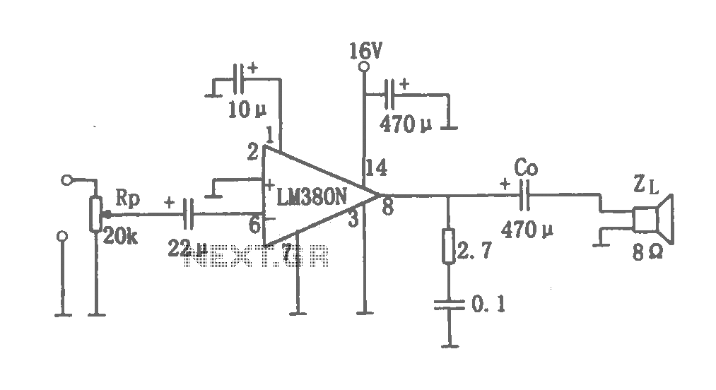
This document details a 2W audio power amplifier circuit that utilizes a 14-pin LM380 package as the amplification element. The input signal is managed by a volume control potentiometer (Rp) rated at 20k ohms, with a coupling capacitance of...