
Capacitor discharge ignition system ( PIC 16F615 )
")
The described circuit employs a PIC12F615 microcontroller, which serves as the control unit for a capacitor discharge ignition system. The primary function of this circuit is to generate high-voltage pulses necessary for igniting a propellant. The ignition process begins when a momentary switch is activated, closing the circuit and allowing the PIC to initiate pulse generation.
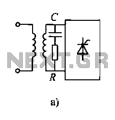
The IRF644 MOSFET is utilized to switch the high voltage to the 1.0 µF capacitor rated at 250 volts. This capacitor is charged through the MOSFET until the voltage reaches a predetermined level of 200 volts, monitored by a voltage divider consisting of a 1MΩ resistor and a 10kΩ resistor. Once the voltage threshold is achieved, the circuit triggers a silicon-controlled rectifier (SCR), which discharges the stored energy into the ignition coil, generating a high-voltage spark across the spark plug.
A 12-volt Zener diode is incorporated into the design to ensure that the capacitor can fully discharge to zero volts, allowing the SCR to reset for subsequent firings. The output spark produced is approximately half an inch in length, which is suitable for igniting the high carbohydrate projectiles used in this application.
The entire electronic assembly, including the momentary switch, is housed within the handle of the device. The design allows for easy access to the projectile loading mechanism by unscrewing the coupling to the barrel. This feature enables the user to breach load the projectiles effectively. Additionally, the rear fitting can be unscrewed to access the main chamber for propellant injection, with lighter fluid cited as an effective choice for this purpose.
To enhance the performance of the projectiles, it is suggested to coat them with flour, preventing them from sticking within the barrel. Care should be taken when using stale projectiles, as they can be propelled with significant force, potentially reaching distances of several hundred feet. Proper maintenance of the chamber, including airing it out between firings, is also recommended to ensure consistent performance.This device uses a PIC12F615 to implement a capacitor discharge ignition system. When the switch (button) is closed, the PIC sends pulses to the IRF644 MosFet creating high voltage pulses to charge the 1.0 uf/250 volt capacitor. The voltage is read back via a 1M/10k divider until 200 volts is reached. Then the SCR (mislabeled triac above) is fired and 200 volts applied to the primary of the ignition coil.
Note, the 12 volt zener is needed to let the capacitor discharge to zero and allow the SCR to reset. The resulting spark is about 1/2 inch to a spark plug with a modified gap. Most of the electronics and momentary switch are located in the handle. Unscrewing the coupling to the barrel allows the (high carbohydrate) projectiles to be breach loaded. Unscrewing the rear fitting access the main chamber to inject the propellant (I've been using lighter fluid in a nasal inhaler bottle - really works great!) - here are some other propellents that we have not tried.
Coating the marshmallows with flour keeps them from sticking in the barrel and improves performance. Watch out when they get a bit stale, they really come flying out then and may go several hundred feet. Don't forget to 'air out' the chamber between firings, or you won't get any real action. Here are the Layout SOURCE and Hex files. 🔗 External reference
Related Circuits

Multi-spark ignition is very useful especially in the case of startings at low temperature and at low rpm range. Basic idea, is to apply to spark plugs instead of only one spark, a spark-burst having big energy. In this...

Creating projects that connect to the phone line can be a real chore without some device like this. It generates the 48 volts DC for the on-hook condition, the 100 volts AC for the ring signal, and the 20...
The Slave Flash Trigger is activated by pressing a push button. When activated, the indicator lamp emits one to three flickers to indicate the programmed mode. One flicker means the flash will fire with each flash, two flickers indicate...
Diodes and thyristors have limited tolerance to over-current and over-voltage conditions. Short-term exposure to excessive voltage or current can damage these components and prevent them from achieving their full potential. The parameters of these devices should be determined based...

The circuit modulates the light emitted by an LED using either a crystal microphone or a loudspeaker output. To achieve maximum range, the optical system must operate efficiently. A convex lens or a concave mirror can be utilized to...

PICkit 2 Introduction: There are many PIC programmers available, including commercial and DIY devices. As Microchip introduces new microprocessors, the programming tools must also evolve to support these advancements. The PICkit 2 is a versatile development tool designed for programming...