
Multi-spark module for Electronic Ignition

1. First spark doesn’t match exactly with the moment of breaking points; so, it has an aleatory delay toward this. This is equivalent to an aleatory modification of ignition advance, which will lead to non-uniform run of engine.
2. At high rpm range, the time between two impulses of multi-spark device can become comparable with the time between breaker-points impulses; this shall lead to an unstable operation of engine, with trepidations and knockings. To avoid this trouble, it is necessary to switch-off the multi-spark device when rpm of engine exceeds a certain value. With these in mind, a device is proposed. The shaping block has the role to provide fixed length impulses (2 mS) at each breaker-points opening. In this way, false impulses which appear due to contacts vibrations are eliminated.
The shaped impulse triggers directly the EID and acts as a START impulse for the multi-spark module. If the rpm of the engine is under the speed limit, the module will generate a series of supplementary impulses that, through an OR gate, will generate supplementary sparks by EID. When the speed limit is reached (for example, 2000 rpm), supplementary impulses stop at the module output, thus no supplementary sparks will be generated. In the multi-spark module, during the 2 mS interval, a sequence timer (a counter with decoded outputs) accomplishes the initialization of circuits. When the impulse BP disappears, the gate P2 is opened and the counter N1 receives impulses with a 1 mS period from a clock generator. This 8-bit counter measures, in fact, the duration between two breaker-points impulses. It can count a maximum of 255 impulses, each having 1 mS (this corresponds to 120 rpm, far below the free running speed). At the next BP impulse, P2 closes and the counting stops. The number stored inside N1 is, in fact, the time length between two BP impulses.
The sequence timer copies the number stored in N1 to N2, after which it resets counter N1. When BP becomes low level, N1 restarts the counting. At the same time, the up/down counter N2 starts counting the impulses having a 0.5 mS period, which come via gate P1. It counts down but at double speed. In this way, the counter N2 reaches ‘0’ after T/2 time. The counter N4 and gate P5 generate the impulses for supplementary sparks (2 mS length). This counter works only if the INH signal is at low level. The flip-flop FF1 marks the interval T/2 in which supplementary sparks will be generated. It is reset when N2 reaches ‘0’. The gates P3 and P4 unlock the flip-flop and start supplementary sparks. These gates also switch-off the multi-spark function when the engine speed limit is reached (in this case, ~2000 rpm).
At approximately 2000 rpm, the time length between two BP impulses is 15 mS. This means that after a counting cycle, the first 4 bits of counter N1 will be 111 and the next 4 will be 0000. In this case, the output of gate P3 will be at low level, and the same value for the output of P4. The flip-flop FF1 will not be set, resulting in no supplementary sparks. If the engine speed decreases (time length T increases), the last 4 bits of N1 will have at least one ‘1’ and the flip-flop will be set. This allows supplementary sparks to appear until the flip-flop is reset by the borrow impulse of N2.Multi-spark ignition is very useful especially in the case of startings at low temperature and at low rpm range. Basic idea, is to apply to spark plugs instead of only one spark, a ?spark-burst? having big energy. In this case, combustion of air/fuel mixture is much better and the emissions are more reduced. In addition, through burning improvement, the consumption of fuel can be reduced. Special literature abounds in multi-spark EID schematics. These have in common the fact, as the breaker-points don?t control directly EID, but an oscillator, which will generate a succession of impulses, and these impulses shall command EID. This aproach has two major deficiencies: 1. First spark doesn?t match exactly with the moment of breaking points; so, it has an aleatory delay toward this.
This is equivalent to an aleatory modification of ignition advance, which will leads to non-uniform run of engine. 2. At high rpm range, the time between two impulses of multi-spark device can become comparable with the time between breaker-points impulses; this shall lead to an unstable operation of engine, with trepidations and knockings.
To avoid this trouble, is necessary to switch-off the multi-spark device when rpm of engine exceeds a certain value. With these in mind, I imagined the device described forwards. Shaping block has the role to provide fixed length impulses (2 mS) at each breaker-points opening. In this way are eliminated the false impulses which appear due contacts vibrations. As shown in drawing, shaped impulse triggers directly the EID and act as START impulse for multi-spark module.
If rpm of engine is under speed limit, the module will generate a series of supplementary impulses that, through an OR gate, will generate supplementary sparks by EID. When speed limit is reached (for example, 2000 rpm), supplementary impulses stops at module output, thus no supplementary sparks will be generated.
In multi-spark module, during 2 mS interval, a sequence timer (a counter with decoded outputs) accomplishes the initialization of circuits (full operations will be detailed later). When impulse BP disappears, the gate P2 is opened and the counter N1 receives impulses with 1 mS period, from clock generator.
This 8 bits counter measures, in fact, the duration between two breaker-points impulses. It can count maximum 255 impulses, each having 1 mS (see the table, this correspond to 120 rpm, far below the free running speed !). At next BP impulse, P2 close and the counting stop. The number stored inside N1 is in fact the time length between two BP impulses. The sequence timer ?copy? the number stored in N1 to N2, after this resets counter N1. When BP becomes low level, N1 restarts the counting. In the same time, the up/down counter N2, starts counting the impulses having 0.5 mS period, which comes via gate P1.
It counts down, but with double speed. In this way the counter N2 reach to ?0? after T/2 time. The counter N4 and gate P5 makes the impulses for supplementary sparks (2 mS length). This counter works only if INH signal is at low level. The fip-flop FF1 ?marks? the interval T/2 in which will be generated supplementary sparks. It is reseted when N2 reach ?0?. The gates P3 and P4 unlock the flio-flop and start supplementary sparks. Also, these gates switch-off the multi-spark function when engine speed limit is reached (in this case, ~ 2000 rpm). How works this ? In the upper table we can see at about 2000 rpm, the time length between two BP impulses is 15 mS. This means as after a counting cycle, the first 4 bits of counter N1 will be 111 and next 4, 0000. In this case, P3 gate output will be at low level, and the same value for P4 output. The flip-flop FF1 will be not set, and as result, no supplementary sparks. If the speed engine decrease (time length T increase), the last 4 bits of N1 will have at least one 1 and the flip-flop will be set.
This allow to appear supplementary sparks until flip-flop will be reseted by borrow impulse of N2. 🔗 External reference
Related Circuits
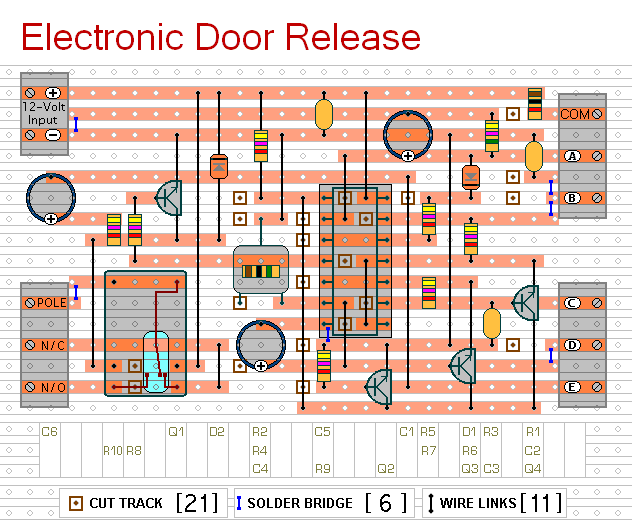
This circuit is designed to operate an electrical door-release mechanism, but it can be adapted for other applications. Upon entering a four-digit code of the user's choice, the relay will energize for a preset duration. The relay contacts can...
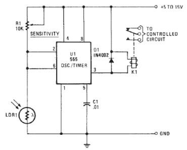
The following circuit illustrates a Photo Alarm Electronic Circuit. This circuit is based on the 555 Timer IC and incorporates features such as an LDR (light-dependent resistor). The Photo Alarm Electronic Circuit utilizes a 555 Timer IC configured in monostable...
This keyer utilizes skin conductivity to emulate the traditional mechanical CW bug keyer. When the dit paddle is activated, the bias on the inverter, IC1-a, is routed to ground, resulting in a logic high output. This triggers oscillator sections...
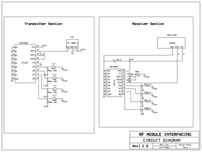
This document presents a circuit example for interfacing an RF module using the HT12E/D encoder-decoder pair. The attached circuit can be utilized for data transmission via the RF module, which is designed for single-channel operation, allowing only serial data...
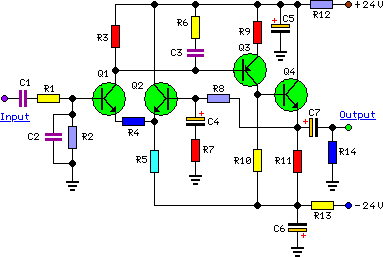
To complement the 60 Watt MOSFET audio amplifier, a high-quality preamplifier design was necessary. A discrete components topology using +24V and -24V supply rails was chosen, minimizing the transistor count while still achieving low noise, very low distortion, and...
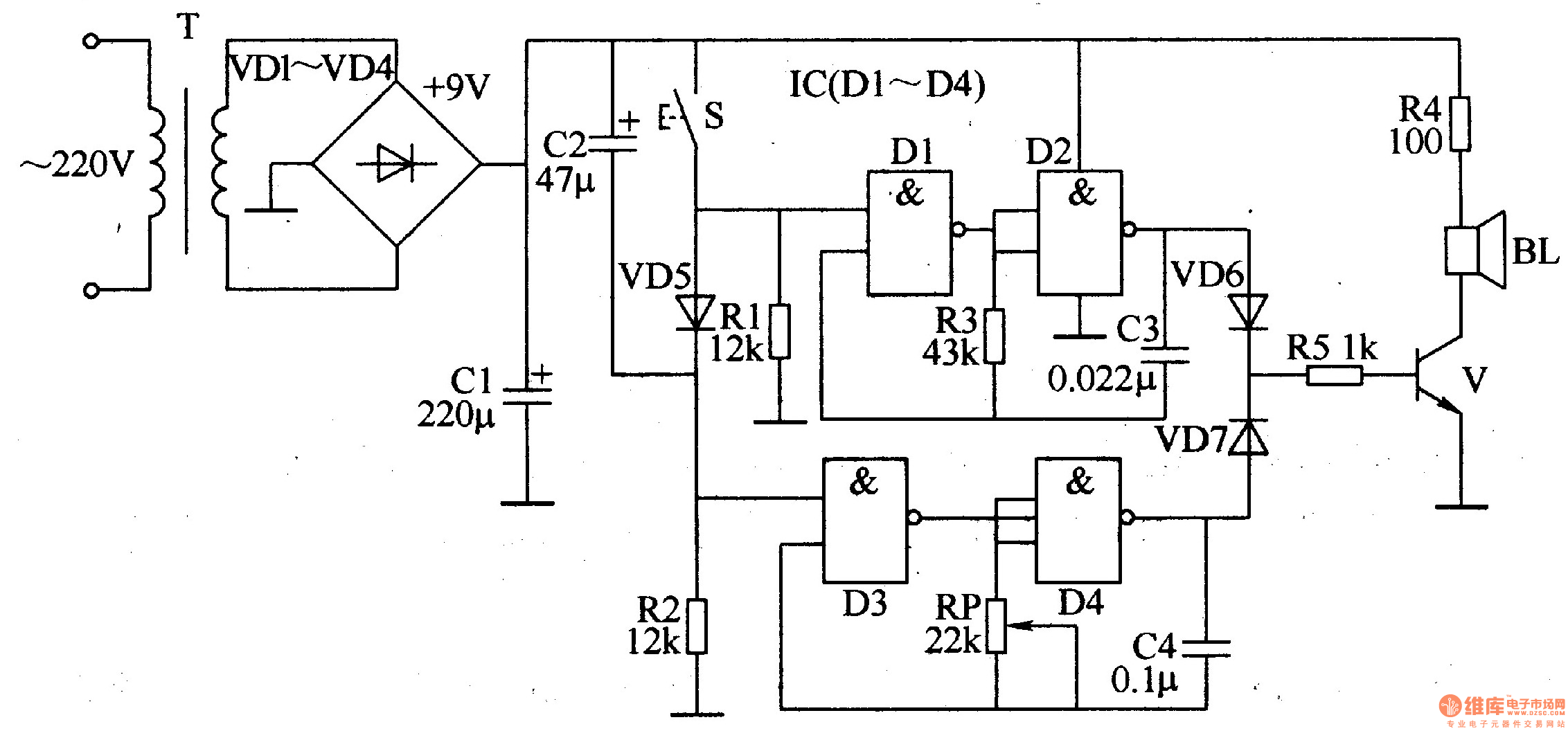
The ding-dong electronic doorbell circuit consists of a power supply circuit, a trigger control circuit, and an audio oscillator output circuit. The power supply circuit includes a power transformer (T), rectifier diodes (VD1-VD4), and a filter capacitor (C1). The...