
Capacitor in parallel with resistor on xoscope amplifier schematic

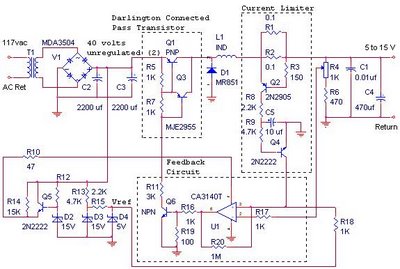
In this circuit, capacitor C3 is strategically positioned across resistor R2 to enhance the stability of the overall system. This configuration is commonly employed in various analog circuits to filter high-frequency noise and improve transient response. The 100pF value of C3 indicates that it is designed to block low-frequency signals while allowing high-frequency signals to pass through, thereby smoothing out fluctuations in voltage across R2.
The presence of C3 can be crucial in preventing oscillations that may arise from feedback loops or other dynamic interactions within the circuit. By providing a low-impedance path for high-frequency signals, C3 helps to maintain the desired performance of the circuit, ensuring that it operates as intended. Without this capacitor, the circuit could experience increased noise susceptibility and potentially unstable behavior, particularly in high-frequency applications.
Understanding the role of C3 in this context is essential for analyzing the circuit's performance. It is important to consider the implications of removing this component, as it could lead to degraded signal integrity and introduce unwanted artifacts in the output. For those new to analog electronics, grasping these concepts will aid in comprehending the intricate balance of components within a circuit and their collective influence on overall functionality.For C3, the 100pF across R2. The circuit does exactly the same thing, once again with no explanation. Apparently the utility ought to be obvious, but I`m new to earnest analog electronics. I can only assume that it`s stabilizing something, but I don`tknow how the operation would suffer without it. 🔗 External reference
Related Circuits
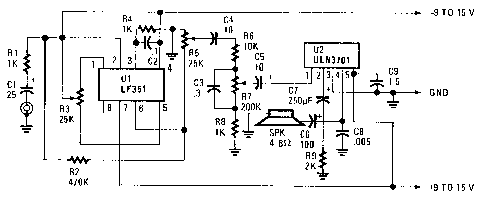
The FET operational amplifier (op amp) requires a bipolar voltage at pins 4 and 7, with a common ground to achieve optimum gain. The gain can be calculated by dividing R2 by R1. Zero-set balance can be achieved through...
There is no substitute for sheer power—low-efficiency speakers, outdoor sound systems, or perhaps the full dynamic range of a high-power amplifier. Whatever the requirement, this super power module should meet the needs. The amplifier can be divided into three...
Individuals seeking private listening to their music should incorporate this Headphone Amplifier into the Modular Preamplifier chain. The circuit design prioritizes simplicity while ensuring high-quality performance. This objective is achieved through the use of two NE5532 Op-Amps, where IC1B...
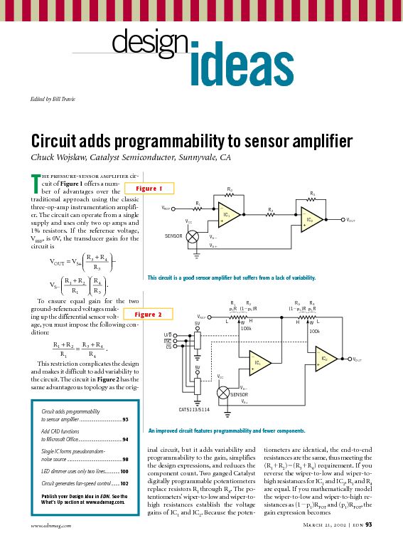
This tutorial provides information related to sensor amplifiers, schematics, and noise. It presents a discussion around sensors and their outputs. Sensor amplifiers are critical components in various electronic systems, especially in applications where signals from sensors need to be conditioned...
The switching power supply provides 12 volts at a maximum of 10 amps, utilizing a discrete transistor regulator with an operational amplifier acting as a comparator in the feedback circuit. The schematic does not depict the front panel power-on...
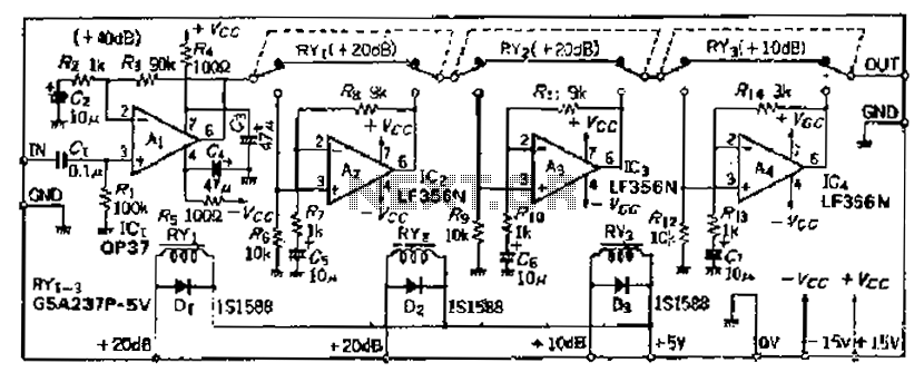
Although the basic amplifier circuit phase AC amplifier remains unchanged, the selection of the correct gain requires the use of series resistors. The circuit does not include a 9kΩ resistor. The input amplifier Ai selected is the OP37, which...