
Available units selected from 10 to 10dB 90dB programmable gain amplifier

The described amplifier circuit utilizes an OP37 operational amplifier as the primary input stage, which is known for its low noise and high precision, making it suitable for applications requiring high gain without significant distortion. The circuit design incorporates a series resistance configuration to optimize the gain setting, ensuring that the desired amplification level is achieved without introducing excessive noise or distortion.
In this configuration, the absence of a 9kΩ resistor suggests a tailored approach to impedance matching and gain selection, which may be crucial for specific signal processing requirements. The use of additional filtering components, such as resistors g5 and chu 5 along with capacitor c4, indicates a proactive measure to mitigate power supply noise, which can adversely affect the performance of sensitive amplifier circuits. This filtering stage is essential in maintaining signal integrity, particularly in environments where electromagnetic interference (EMI) is prevalent.
The circuit's design allows for the use of standard operational amplifiers for stages Ai and As, provided that they meet the necessary specifications, particularly in terms of slew rate. A minimum conversion rate of 10 V/s is mandated to ensure that the amplifier can respond adequately to rapid changes in input signals without introducing lag or distortion.
To further enhance performance, the inclusion of a 1011F capacitor in the amplifier stage is a strategic choice aimed at stabilizing the DC offset voltage. This component helps to maintain the desired operating point of the amplifier, ensuring that the gain remains consistent at a factor of 10. This careful balance of components and design principles is fundamental in achieving a high-performance amplifier circuit that meets the requirements of modern electronic applications.Although the basic amplifier circuit phase AC amplifier are the same, no special change, but in order to select the correct magnification, the circuit uses ugly series resistan ce does not have 9k0. Resistance. The input amplifier Ai selected OP37 (even if magnification is large, deterioration of properties is small, does not fill phase compensation) in order to remove the power supply line broadband noise, the circuit increased by the clamor, g5 and chu 5, c4 filter constituted. Although Ai ~ As can adopt a common OP amplifier, but the conversion rate should be 10 V/s or more. In order not to increase the DC offset voltage amplifier stage equipment are used 1011F electric vessel so that the flow at a magnification of 10 wins
Related Circuits
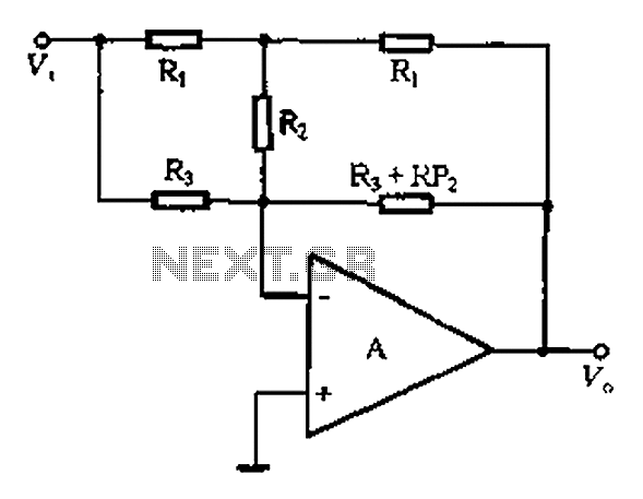
At high frequencies, the capacitor Cz can be considered a short circuit (i.e., the resistance of the RPi is negligible). This is illustrated in Figure 4-6 (a) of the apparatus, which corresponds to the equivalent circuit shown in Figure...
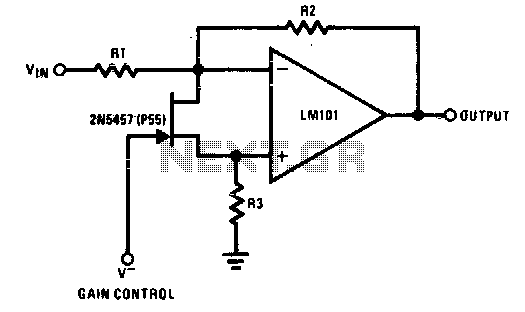
The 2N5457 functions as a voltage-variable resistor with a maximum RdS of 800 ohms. Given that the differential voltage on the LM101 is in the low millivolt range, the 2N5457 JFET exhibits linear resistance over several decades, offering excellent...
It is important to note that there is limited protection circuitry and fuses in this amplifier. A short turn-on delay for the output power supply is included to minimize thumps, along with a couple of line fuses, but no...
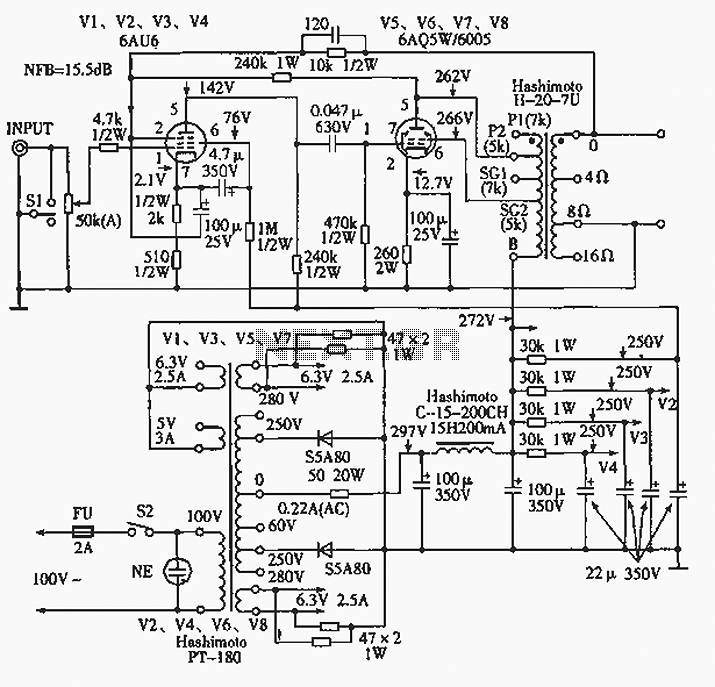
The 6AQ5W / 6005UL four-channel single-ended amplifier circuit is illustrated in the accompanying figure. Only two channels are shown, but it is part of a four-channel system that employs a power transformer for the voltage amplification section. This section...

A gain stage is being constructed using Decware's Zkit4 to serve as a buffer in front of an LM3875 gain clone. The chip amplifier has sufficient... The gain stage circuit designed using Decware's Zkit4 is intended to provide impedance matching...
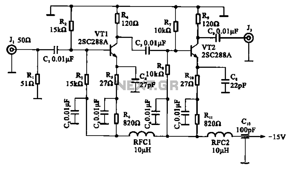
A wideband high-frequency amplifier circuit is presented, utilizing resistance and capacitance coupling in a common emitter configuration to amplify high-frequency signals. When a high-frequency signal with an input impedance of 50 ohms is applied to the amplifier through a...