
40W audio amplifier based on TDA1514 circuit diagram

The car stereo circuit integrates various components to achieve high-quality audio output. The Class B audio amplifier is particularly noteworthy for its efficiency and ability to deliver a significant amount of power with minimal distortion. This amplifier uses two transistors, each responsible for amplifying one half of the audio signal, which is characteristic of Class B operation.
In the circuit, the LM833 dual op-amp serves as the input stage, providing necessary signal conditioning and gain before the signal is passed to the output stage. The op-amp configuration ensures that the audio signal is amplified with high fidelity. The output stage consists of complementary transistors that work in tandem to amplify the signal. This arrangement allows for a more efficient operation, reducing the heat generated compared to Class A amplifiers.
The circuit diagram typically includes power supply connections, input and output terminals, and biasing resistors that set the operating point of the transistors. Proper biasing is crucial for the linear operation of the transistors, ensuring that they do not enter cutoff or saturation during operation.
Additionally, capacitors may be included in the circuit to filter out noise and provide stability, while feedback resistors are used to control gain and improve linearity. The overall design ensures that the amplifier can drive speakers effectively, delivering a clean and powerful audio output suitable for automotive applications.Here is a circuit diagram of car stereo. Below is a circuit diagram of class B 15 Watts audio amplifier is designed using a dual op-amp and transistor. The 15 W class B audio amplifier circuit shown here is a simple class B audio amplifier based onLM833 op.
🔗 External reference
Related Circuits

This USB to Serial RS232 adapter is highly beneficial in scenarios where a device with RS232 needs to be connected to a computer lacking an RS232 port but equipped with a USB port. Utilizing the FT232BM chip produced by...
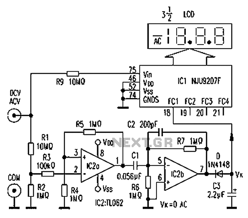
The circuit depicted in the figure illustrates an automatic AC/DC converter for a digital multimeter. Typically, standard digital multimeters require manual intervention to switch between AC and DC measurements. The new DT860D digital multimeter utilizes the NJU9207F automatic range...
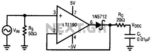
This closed-loop peak detector circuit utilizes a Schottky diode within the feedback loop to achieve high accuracy. The 20-ohm resistance RQ serves to isolate the 0.01-ohm load and prevent oscillations. The direct current (DC) value is measured using a...
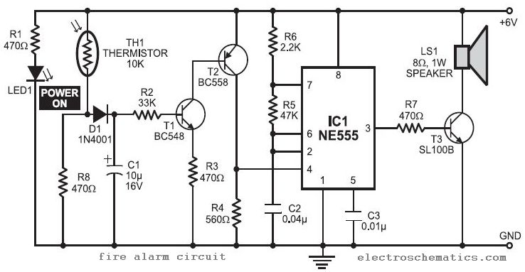
In this fire alarm circuit project, a thermistor functions as the heat sensor. When the temperature rises, its resistance decreases, and conversely, when the temperature falls, its resistance increases. Under normal conditions... In this fire alarm circuit, the thermistor is...
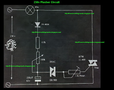
This circuit operates at 230V and can be utilized for party decoration purposes. It is sourced from an old circuit book titled "100 Circuit Book." The components include DIAC ER 900 and TRIAC BTW 11-400. The circuit is designed to...
This is a clap switch designed to avoid false triggering. To activate or deactivate any appliance, a user must clap twice. The circuit changes its output state only when two claps are detected within a specified time frame of...