
Car Alarm and Immobilizer

The described circuit is a vehicle security system that incorporates several key features to enhance the protection of the vehicle. The exit and entry delays allow the user time to disarm the alarm after exiting the vehicle and to enter without triggering the alarm immediately. This is achieved by connecting the alarm system to the vehicle's existing door switches, which are typically wired in parallel. The circuit can be simplified by utilizing a single wire connection to one of the door switches, as this will suffice to monitor the status of all doors.
For added functionality, the system can include external relays that enable the immobilization of the vehicle and the activation of flashing lights. This is particularly useful for deterring unauthorized access or theft. The siren output is designed to be intermittent, providing an audible alert without continuous noise, which can be more effective in drawing attention without causing undue disturbance.
The activation of the alarm is initiated by opening a switch (Sw1), which can be a standard single-pole change-over switch rated for 1 amp. To enhance security, a key-switch can be employed as an alternative to prevent unauthorized access to the alarm setting feature. Once Sw1 is opened, a delay of approximately 10 to 15 seconds is provided for the user to exit the vehicle and close the door. This time allowance ensures that the alarm does not trigger while the user is still within the vehicle.
Additional normally-open switches can be incorporated into the door circuit to enhance the system's functionality, although care must be taken to ensure that these switches can handle the current required for the vehicle's interior light. This consideration is crucial to maintain the reliability and safety of the overall system. The automatic reset feature ensures that the alarm system returns to a standby state after activation, reducing the likelihood of false alarms while maintaining readiness to respond to any unauthorized entry attempts.This circuit features exit and entry delays, an instant alarm zone, an intermittent siren output and automatic reset. By adding external relays you can immobilize the vehicle and flash the lights. One of the inputs is connected to the vehicle`s existing door-switches. This provides the necessary exit and entry delays. It`s usually sufficient to connect a SINGLE wire to just ONE of the door switches - they`re generally all connected in parallel with the return through the chassis.
You can add extra normally-open switches to the door-circuit if you wish; but note that any additional switches will have to be able to carry the current required by your vehicle`s interior light. The alarm is "set" by opening Sw1. It can be any small 1-amp single-pole change-over switch - but for added security you could use a key-switch. Once Sw1 is opened you have about 10 to 15 seconds to get out of the vehicle and close the door behi 🔗 External reference
Related Circuits
A pair of cross-coupled SCRs can be utilized to create a first-response monitor circuit, as illustrated in the schematic diagram below. The first-response circuit is... In the context of electronic monitoring systems, a first-response monitor circuit employing cross-coupled Silicon Controlled...
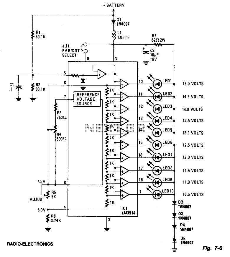
This screen utilizes ten LEDs to indicate a voltage range from 10.5 to 15 volts, with each LED corresponding to a 0.5-volt increment. The core component of the circuit is the LM3914 LED bar graph/display driver. A trimming potentiometer,...
Pulses are received by the timer from the distributor points. When the timer output is high, Meter M receives a calibrated current through R6. The meter does not... The circuit described involves a timer that receives pulse signals from distributor...
This circuit can be constructed using readily available, low-cost components, some of which may even be found in a junk box. The specified value of 22 for resistor R1 results in an average current of approximately 65 mA flowing...

The automatic alarm circuit comprises a DTMF automatic dialing system, a password control circuit, a voice detection and alarm circuit, a telephone interface circuit, a power supply circuit, and a keyboard display circuit. The automatic dial-up alarm utilizes the...
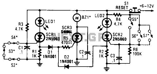
In this circuit, a low-powered silicon-controlled rectifier (SCR) is utilized to trigger a higher-powered SCR. When a switch is opened (S2, S3, S4) or closed (S5, S6, S7), either SCR1 or SCR2 is activated. This action subsequently triggers SCR3...