
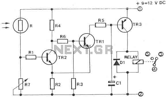
Car Alarm Security Circuit

The car alarm circuit is designed to enhance vehicle security by providing timely alerts to unauthorized access. The 18-second delay allows users to enter or exit the vehicle without triggering the alarm, offering convenience while maintaining security. During this delay period, any unauthorized attempt to open the doors or manipulate the sensors will activate the alarm system.
Once triggered, the alarm emits a continuous sound for 6 minutes, which serves as both a deterrent to potential intruders and a notification to the vehicle owner. After this duration, the system automatically disables the horn, ensuring that it does not continue to sound indefinitely, which could lead to unnecessary disturbances.
The design of the alarm circuit includes a robust feature that keeps the alarm activated regardless of whether the doors are closed or if other sensor switches are engaged. This ensures that even if an intruder attempts to disable the system by manipulating the door locks or other entry points, the alarm will still function as intended, providing an additional layer of security.
Overall, the car alarm circuit is an effective solution for protecting vehicles from theft and unauthorized access, offering both a user-friendly experience and reliable performance in various scenarios.This car alarm circuit offers 18 seconds delay for the entrance and the exit. It sound continually for 6 minutes and automaticaly turns horn off and gets ready for the next trigering... The Alarm stays ON even if you close the doors or open other sensor switch.
Related Circuits
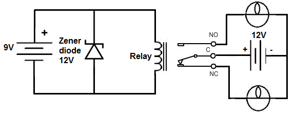
This project involves the construction of a relay driver suitable for both DC and AC relays. Since DC and AC voltages operate differently, the setups for their respective relay drivers require slight variations. A generic relay driver that can...
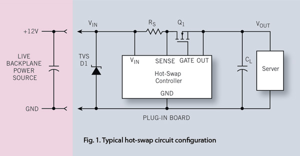
To ensure reliability, the server system designer must take into account the parasitics of hot-swap circuits and their associated transient behavior. It is recommended that a transient voltage suppressor (TVS) diode clamp be utilized at the line card input....
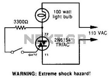
A triac can be utilized as a line-operated AC power switch that directly controls lamps, heaters, or motors. A brief current pulse into the gate activates the triac, and it remains on until the main current reverses. A triac, or...
The impedance of these current generators is essentially infinite for small currents, and they maintain accuracy as long as VIN is significantly greater than VOS and IO is much higher than I bias. The source employs a FET to...
The circuit is a light switch that activates when the light intensity drops on a photoresistor. It features a straightforward construction and can be utilized in numerous applications. The photoresistor and the trimmer function as a voltage divider and...
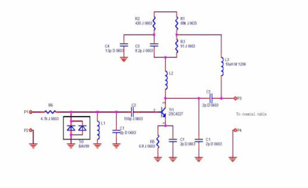
A flat mobile active car antenna is being tested with a Terratec Cinergy DT USB XS Diversity digital tuner. The antenna is designed to enhance signal reception for mobile digital television. The flat mobile active car antenna is engineered to...