
Simple light-switch circuit

This circuit operates as a light-sensitive switch, making it ideal for applications such as automatic lighting systems, security lights, or garden lights that turn on at dusk. The core component of the circuit is the photoresistor, which changes its resistance based on the ambient light level. As light intensity decreases, the resistance of the photoresistor increases, affecting the voltage across it.
The voltage divider formed by the photoresistor and the trimmer (R7) is critical for setting the threshold at which the circuit activates. The trimmer allows for fine-tuning of sensitivity, enabling the user to adjust the light level required to trigger the switch. When the voltage across the photoresistor reaches a certain level, it provides enough base current to turn on transistor TR1.
Transistor TR1, being an NPN type, conducts when its base receives sufficient voltage, allowing current to flow from the collector to the emitter. This action turns on transistor TR2, which operates in a similar manner, amplifying the current to drive the relay. The relay, rated for 12V, serves as the output mechanism that can control larger loads, such as lights or other electrical devices, by switching them on or off based on the light conditions detected by the photoresistor.
The circuit also includes a diode (D1) connected in parallel with the relay to protect the transistors from back EMF generated when the relay coil is de-energized. Capacitor C1 acts as a filter capacitor, smoothing out any voltage fluctuations in the circuit, ensuring stable operation.
The combination of these components results in a reliable light-activated switch that can be adapted for various uses, providing a practical solution for automatic lighting control in different environments.The circuit is a light switch who triggers when light drops on photo resistor. It is fairly simple in construction and can be used in a million applications. The photoresistor and the trimmer work as a voltage divider and also polarize the transistor TR1. TR1 triggers TR2 and TR2 drives the relay. Trimmer R7 is for adjusting the sensitivity of the circuit. Parts: R = photoresistor R1= 4.7 Kohm R2= 1.2 Kohm R3= 2.2 Kohm R4= 1.2 Kohm R5= 1.2 Kohm R6= 2.7 Kohm R7= 100Kohm Trimmer C1 = 10uf/16V electrolytic TR1= BC107 - BC108 NPN TR2= BC107 - BC108 NPN TR3= BC557 - BC558 PNP - BC327 D1 = 1N4148 Relay = any 12Volt relay
Related Circuits
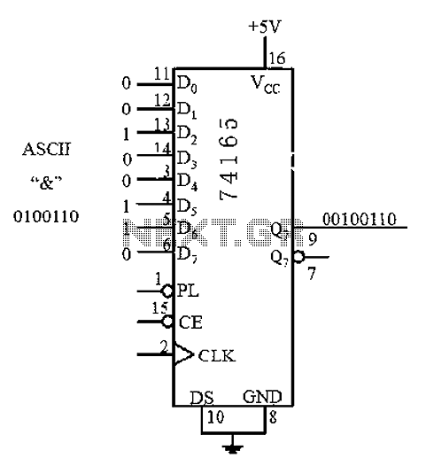
An 8 parallel input/serial output interface circuit. An 8 parallel input/serial output interface circuit is designed to convert multiple parallel data inputs into a single serial output stream. This type of circuit is commonly used in digital systems where data...

The inverting input is maintained at a low level via a 10K resistor when the circuit is powered on but not in use. During measurement activities, including calibration measurements where the input is floating, this resistor is disconnected. The...
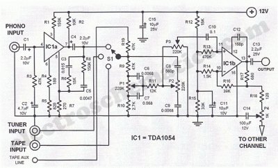
This Hi-Fi stereo preamplifier circuit is constructed using the TDA1054 integrated circuit (IC) from SGS. The TDA1054 is housed in a 16-pin DIL package and incorporates two separate preamplifier circuits. It is characterized by low noise and minimal issues...
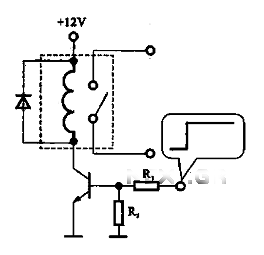
A relay control circuit is illustrated, which is commonly found in microwave switches. This circuit facilitates the operation of various components such as the power supply switch, electric fans, light bulbs, food turntables, and timers. The relay control signal...
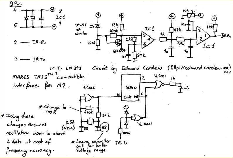
A TSOP4156 is often difficult to obtain or expensive to purchase. In response, an individual utilized old BPW41 infrared diodes to construct a custom receiver. The power source is derived from the RS232 port, requiring a minimum of 5.5...
This circuit utilizes a relay to control a water pump, enabling automatic level management of a water reservoir or well. The shorter steel rod functions as the "water high" sensor, while the longer rod serves as the "water low"...